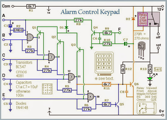
Let’s rollback the hobby electronics calendar a few decades with [myvideoisonutube's] alarm activation control circuit using a matrix style phone keypad. The circuit is quite old using CMOS 4081 with 4 ‘AND’ gates to hardwire the access code. [myvideoisonutube] references [Ron’s] “Enhanced 5-Digit Alarm Keypad” schematic for this build changing the recommend keypad with a more common matrix style keypad found in touch pad phones.
These types of matrix keypads wouldn’t work outright for the input so he cut some traces and added hookup wires to transform it into a keypad with common terminals and separately connected keys. We love seeing such hacked donor hardware even when it requires extensive modifications. [Ron's] source circuit included a simple enough to build tactical button keypad if you can’t find a suitable donor phone.
Learning how to use mostly discrete components instead of a microcontroller would be the core objective to build this circuit outside of needing a key-code access point or other secure 12 V relay activated device. Such a device would be quite secure requiring a 4 digit “on” code and 5 digits for “off”. You couldn’t just pull off the keypad and hotwire or short something to gain access either. The 4 digit on “feature” does knock the security down quite a lot. However, all keys not in the access code are connected to the same point so you could increase your security by using a pad with more keys.
On [Ron’s] site you will find a detailed construction guide including top and bottom view for placement of all the components on veroboard. Join us after the break to watch [myvideoisonutube] demo his version.

0 comments:
Post a Comment