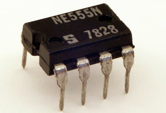
[fahadshihab], a young tinkerer, shared his circuit design for a simple remote control using 555 timers. Using a 555 calculator, he designed a clock circuit that would run at 11.99 Hz. Two transistors are connected to inputs (presumably button switches). One sends the plain clock signal, and one sends the inverted clock signal. A matching circuit at the other end will separate the channels. All it requires is connecting the two circuits in order to synchronize them. It would be easy enough to interface this with an oscillator, an IR LED, or a laser for long-range control.
The great thing about this circuit is its simplicity. It’s often so easy to throw a microcontroller into the mix, that we forget how effective a setup like this can be. It could also be a great starter circuit for a kid’s workshop, demonstrating basic circuits, timers, and even a NOT gate. Of course, it would be a good refresher for those without a lot of circuit knowledge too. Once you’ve mastered this, perhaps an AM transmitter is next?
The great thing about this circuit is its simplicity. It’s often so easy to throw a microcontroller into the mix, that we forget how effective a setup like this can be. It could also be a great starter circuit for a kid’s workshop, demonstrating basic circuits, timers, and even a NOT gate. Of course, it would be a good refresher for those without a lot of circuit knowledge too. Once you’ve mastered this, perhaps an AM transmitter is next?

0 comments:
Post a Comment