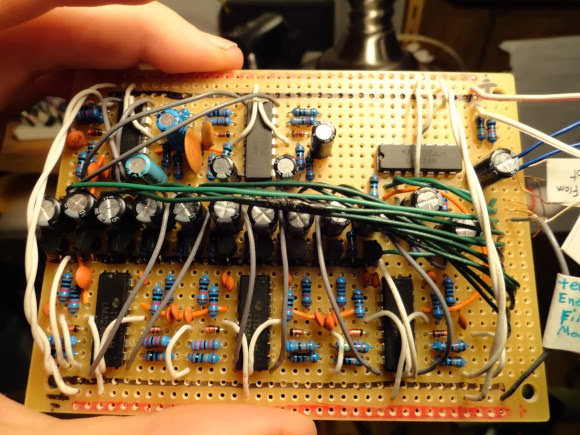
[Ryan] wanted a spectrum analyzer for his audio equipment. Rather than grab a micro, he did it the analog way. [Ryan] designed a 10 band audio spectrum analyzer. This means that he needs 10 band-pass filters. As the name implies, a band-pass filter will only allow signals with frequency of a selected band to pass. Signals with frequency above or below the filter’s passband will be attenuated. The band-pass itself is constructed from a high pass and a low pass filter. [Ryan] used simple resistor capacitor (RC) filters to implement his design.
All those discrete components would quickly attenuate [Ryan's] input signal, so each stage uses two op-amps. The first stage is a buffer for each band. The second op-amp, located after the band-pass filters, is configured as a non-inverting amplifier. These amplifiers boost the individual band signals before they leave the board. [Ryan] even added an “energy filler” mode. In normal mode, the analyzer’s output will exactly follow the input signal. In “energy filler” (AKA peak detect) mode, the output will display the signal peaks, with a slow decay down to the input signal. The energy filler mode is created by using an n-channel FET to store charge in an electrolytic capacitor.
Have we mentioned that for 10 bands, all this circuitry had to be built 10 times? Not to mention input buffering circuitry. With all this done, [Ryan] still has to build the output portion of the analyzer: 160 blue LEDs and their associated drive circuitry. Going “all analog” may seem crazy in this day and age of high-speed micro controllers and FFTs, but the simple fact is that these circuits work, and work well. The only thing to fear is perf board solder shorts. We think debugging those is half the fun.

0 comments:
Post a Comment