Overhauling an IC Programmer

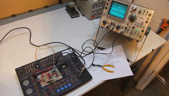
[NeXT] needed an EPROM programmer to work with chips from vintage computers. Starting with a low cost programmer, he built this custom IC programmer to handle all of his programming needs.
The device is based on the Willem 5.0e programmer. [NeXT] was not satisfied with the device, noting that it had to be carefully isolated from metal surfaces during use and required setting many annoying jumpers.
Overhauling an IC Programmer
To solve these problems, he started off by dismantling the programmer. The IC sockets were moved to a daughter board, which could be mounted cleanly into the metal enclosure. Replacing the jumpers was a bit more complicated, a combination of toggle and rotary switches were chosen to make changing settings easier. Soldering the boards together looks like it was not an easy task, with 200 solder joints needed to connect the sockets and switches. After debugging some shorts and dead connections, [NeXT] managed to finish the 1.5 year project right before his Christmas deadline.
read the rest of article...

Acoustic Delay Line Memory

Back in the olden days  when computers were both analog and digital, making RAM was actually very hard. Without transistors, the only purely electronic means of building a memory system was vacuum tubes; It could have been done, but for any appreciable amount of RAM means an insane amount of tubes, power, and high failure rates.
Acoustic Delay Line Memory
One of the solutions for early RAM was something called a delay line. This device used ultrasonic transducers to send a pulse through a medium (usually mercury filled tubes heated to 40°C) and reads it out at the other end. The time between the pulse being sent and received is just enough to serve as a very large, small capacity RAM. Heated tubes filled with hundreds of pounds of mercury isn’t something you’d want sitting around for a simple electronics project. You can, however, build one out of a Radio Shack Electronics Learning Lab, a speaker, and a microphone.

[Joe] designed his delay line using an op-amp to amplify the train of acoustic pulses traveling through the air. A compactor picks up these pulses and sends them into a flip-flop. A decade counter and oscillator provide the timing of the pulses and a way to put each bit in the delay line. When a button on the electronics lab is pressed, a ‘tick’ is sent into the speaker where it travels across [Joe]‘s basement, into the microphone, and back into the circuit. The entire setup is able to store ten bits of information in the air, with the data conveniently visualized on an oscilloscope. It’s not a practical way to store data in any way, shape, or form, but it is an interesting peek into the world before digital everything.

Video below.

read the rest of article...

[Fran]‘s LEDs, Nixies, and VFDs.

With a love of blinky and glowey things, [Fran] has collected a lot of electronic display devices over the years. Now she’s doing a few teardowns and tutorials on some of her (and our) favorite parts: LEDs and VFD and Nixie tubes Perhaps it’s unsurprising that someone with hardware from a Saturn V flight computer also has a whole lot of vintage components, but we’re just surprised at how complete [Fran]‘s collection is. She has one of the very first commercial LEDs ever made. It’s a very tiny red LED made by Monsanto (yes, that company) packaged in a very odd lead-and-cup package.
[Fran]‘s LEDs, Nixies, and VFDs.
Also in her LED collection is a strange Western Electric part that’s green, but not the green you expect from an LED. This LED is more of an emerald color – not this color, but more like the green you get with a CMYK process. It would be really cool to see one of these put in a package with red, green, and blue LED, and could have some interesting applications considering the color space of an RGB LED.

Apart from her LEDs, [Fran] also has a huge collection of VFD and Nixie tubes. Despite the beliefs of eBay sellers, these two technologies are not the same: VFDs are true vacuum tubes with a phosphorescent coating and work something like a CRT turned inside out. Nixies, on the other hand, are filled with a gas (usually neon) that turns to plasma when current flows through one of the digits. [Fran] has a ton of VFDs and Nixies – mostly military surplus – and sent a few over to [Dave Jones] for him to fool around with. It’s all very cool stuff and a great lead-in to what we hear [Fran] will be looking at next: electroluminescent displays found in the Apollo Guidance Computer.

Videos below.


read the rest of article...

Build an Audio Spectrum Analyzer the Analog Way

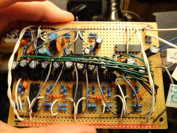
[Ryan] wanted a spectrum analyzer for his audio equipment. Rather than grab a micro, he did it the analog way. [Ryan] designed  a 10 band audio spectrum analyzer. This means that he needs 10 band-pass filters. As the name implies, a band-pass filter will only allow signals with frequency of a selected band to pass. Signals with frequency above or below the filter’s passband will be attenuated. The band-pass itself is constructed from a high pass and a low pass filter. [Ryan] used simple resistor capacitor (RC) filters to implement his design.
Build an Audio Spectrum Analyzer the Analog Way
All those discrete components would quickly attenuate [Ryan's] input signal, so each stage uses two op-amps. The first stage is a buffer for each band. The second op-amp, located after the band-pass filters, is configured as a non-inverting amplifier. These amplifiers boost the individual band signals before they leave the board. [Ryan] even added an “energy filler” mode. In normal mode, the analyzer’s output will exactly follow the input signal. In “energy filler” (AKA peak detect) mode, the output will display the signal peaks,  with a slow decay down to the input signal. The energy filler mode is created by using an n-channel FET to store charge in an electrolytic capacitor.

Have we mentioned that for 10 bands, all this circuitry had to be built 10 times? Not to mention input buffering circuitry. With all this done, [Ryan] still has to build the output portion of the analyzer: 160 blue LEDs and their associated drive circuitry. Going “all analog” may seem crazy in this day and age of high-speed micro controllers and FFTs, but the simple fact is that these circuits work, and work well. The only thing to fear is perf board solder shorts. We think debugging those is half the fun.
read the rest of article...

Apple And Raspberry Pis

Deep in the bowels of the Internet there are some crazy people who have a wish list for what the next Apple II should look like. The capabilities of this dream machine of 80s retrocomputing is generally said to be something with a 32-bit CPU, a UNIX OS, modern graphics, and networking. This sounds a lot like a Raspberry Pi, so [Dave] built an Apple II to Raspberry Pi adapter card.
Apple And Raspberry Pis
Having a Pi talk to an Apple II over a serial connection doesn’t really give either machine the full capabilities of the other. To fix this issue, [Dave] wrote two pieces of software. The first is a UNIX daemon that listens to the Apple II on a serial port connection, handling the Apple II keyboard connection. The second piece of software is a ProDOS disk image file running on the Apple II. With these two pieces of software, [Dave] can run the Apple on the Raspi, or run the Raspi on the Apple, sending files and data back and forth with no problem.

Aside from providing a strange and awesome Apple II to UNIX interface, the Apple II Pi also has a lot of advantages that might not be readily apparent. An Apple II compact flash adapter can be used as an internal hard drive for these pieces of classic apple hardware, and the Uthernet Ethernet card for the AII brings networking. Both of these devices are absurdly expensive compared to the component cost of the Apple II Pi, and what they bring to the table can be easily copied by the Apple II Pi.

The Apple II Pi is just a simple double-sided board with a few resistors, a cap, header, a 7404 inverter, and a communications chip that’s $5 for quantity one. If you already have a Raspi hanging around your workbench and want to soup up an Apple II with some crazy hardware capabilities, you really can’t do better than getting one of these Apple II Pi boards. Now if we could only find the board files…

Video of the Apple II Pi below, showing off all the awesome capabilities of a Pi-powered Apple. Thanks [Itay] for sending this one in.

read the rest of article...

Further Teardown of the Saturn V Flight Computer

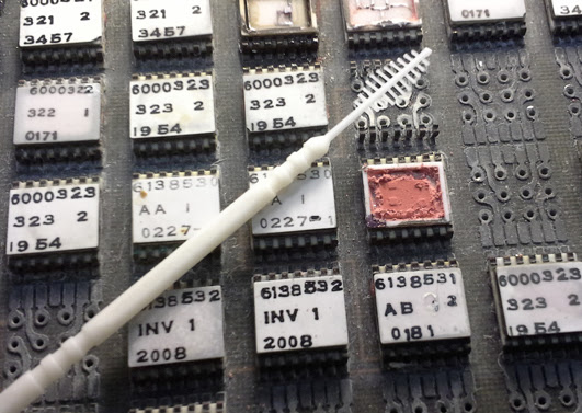
[Fran] has been working on tearing down and reverse engineering the Saturn V Launch Vehicle Digital Computer (LVDC). In her finale, she’s succeeded in depotting the legacy components while keeping them intact. She accomplished this by carefully removing the silicone compound using a gum brush. This was a laborious process, but it allowed her to see the device’s innards. With this knowledge, she could recreate the logic modules on a breadboard.
Further Teardown of the Saturn V Flight Computer
[Fran]‘s work on the LVDC has been very interesting. It began with a look at the PCB, followed by an x-ray analysis. Next up was a three part series of the teardown. With each part is a detailed video on the progress. While this is the end of [Fran]‘s work on the project, she will be handing off the LVDC hardware to another engineer to continue the analysis. We’re looking forward to seeing what comes out of this continued research.
read the rest of article...

Reverse Engineering an LCD Display

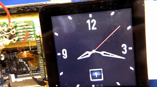
The current marketplace allows hobbyists to easily find inexpensive, well-documented displays, but what if you wanted to interface with something more complicated, such as the screen on an iPod Nano 6? [Mike] has given us a detailed and insightful video showing his process for reverse engineering a device with little-to-no documentation.
Reverse Engineering an LCD Display
Here he covers the initial investigation, where one scours the web in search of any available information. In [Mike's] example, the display uses an MIPI D-PHY interface, which he has never worked with. He learns that the MIPI Alliance will provide design specs in exchange for a signed NDA (Non-Disclosure Agreement) and a modest $8000 fee. Nice.


[Mike] shows off some serious hardware hackery, tackling some extremely difficult soldering in order to set up a proper test platform. He then demonstrates how to use a rather awesome oscilloscope to better understand the display protocol. We found it fascinating to see the video signals displayed as waveforms, especially when he shows how it is possible to count the individual binary values. The amount of information he uncovers with the oscilloscope is nothing short of amazing, proving these little devices are more complex than they seem.

[via Hacked Gadgets]
read the rest of article...

Reverse Engineering Serial Ports

Can you spot the serial port in the pic above? You can probably see the potential pads, but how do you figure out which ones to connect to? [Craig] over at devttys0 put together an excellent tutorial on how to find serial ports. Using some extreme close-ups, [Craig] guides us through his thought process as he examines a board. He discusses some of the basics every hobbyist should know, such as how to make an educated guess about which ports are ground and VCC. He also explains the process to guessing the transmit/receive pins, although that is less straightforward.
Reverse Engineering Serial Ports
Once you’ve identified the pins, you need to actually communicate with the device. Although there’s no easy way to guess the data, parity, and stop bits except for using the standard 8N1 and hoping for the best, [Craig] simplifies the process a bit with some software that helps to quickly identify the baud rate. Hopefully you’ll share [Craig's] good fortune if you reach this point, greeted by boot messages that allow you further access.
read the rest of article...

Veronica Gets A Pair Of Gamepads And A Bugged Chip

[Quinn Dunki]‘s awesome 6502-based computer is coming right along, and she decided it’s time to add one of the most important features found in the 80s microcomputers she’s inspired by – gamepads. There were two ways of implementing gamepads back in the 80s. The Apple II analog joysticks used a potentiometer for each joystick axis along with a 556 timer chip to convert the resistance of a pot into a digital value.
Veronica Gets A Pair Of Gamepads And A Bugged Chip
Analog controls are awesome, but a lot of hardware is required. The other option is the Atari/Commodore joystick that uses buttons for each direction. Surprisingly, these joysticks are inordinately expensive on the vintage market but a similar hardware setup – NES gamepads – are common, dirt cheap, and extremely well documented.

[Quinn] wrote a few bits of 6502 assembly to read these Nintendo controllers with Veronica’s 6522 VIA with the help of an ATMega168, and then everything went to crap.
In testing her setup, she found that sometimes the data line from the controller would be out of sync with the clock line. For four months, [Quinn] struggled with this problem and came up with one of two possible problems: either her circuit was bad, or the 6522 chip in Veronica was bad. You can guess which option is correct, but you’ll probably be wrong.

The problem turned out to be the 6522. It turns out this chip has a bug when it’s used with an external clock. In 40 years of production this hasn’t been fixed, but luckily 6502 wizard [Garth Wilson] has a solution for this problem: just add a flip-flop and everything’s kosher. If only this bug were mentioned in the current datasheets…
Now Veronica has two NES controller inputs and the requisite circuitry to make everything work. Video evidence below.
read the rest of article...

Internet-Enabling a Lamp with the Raspberry Pi

[Jack] sent in his writeup for internet enabling a home lamp. While we will certainly have some comments saying this is too simple, it does a great job of breaking things down to the basics. For those that aren’t confident in their electronic skills, this is an easy hack to a commercial device that greatly expands it’s capabilities. [Jack] started with a cheap wireless outlet controller.
Internet-Enabling a Lamp with the Raspberry Pi
By opening the remote and wiring each switch to a 2N222A transistor, you can very easily control the remote from the GPIO pins on the Raspberry Pi. In [Jack's] case, he set up a web page using Flask that allows quick on/off control.

Of course, this method can be used in any number of instances where you have a wireless controller, from small lamps to garage doors. Given it’s simplicity, anyone can do it with even basic skills. If you’re a beginner who’s been itching to do some home automation, follow [Jack's] writeup and check an item off your todo list!
read the rest of article...

VFD And Nixie Clock Twofer

Sometimes the stars align and we get two somewhat similar builds hitting the Hackaday tip line at the same time. Recently, the build of note was clocks using some sort of display tube, so here we go. First up is [Pyrofer]‘s VFD network time clock (pic, above). The build started as a vacuum flourescent display tube he salvaged from an old fruit machine – whatever that is. The VFD was a 16 character, 14 segment display, all controlled via serial input.
VFD And Nixie Clock Twofer
The main control board is, of course, an Arduino with a WizNet 5100 Ethernet board. The clock connects to the Internet via DHCP so there’s no need to set an IP address. Once connected, the clock sets itself via network time and displays the current date, time, and temperature provided by a Dallas 1-wire temperature probe. Next up is [Andrew]‘s beautiful Nixie clock with enough LEDs to satiate the desires of even the most discerning technophile. The board is based on a PIC microcontroller with two switching power supplies – one for the 170VDC for the Nixies, and 5V for the rest of the board.

A battery backed DS1307 is the real-time clock for this board, and two MCP23017 I/O expanders are used to run the old-school Nixie drivers
All this is pretty standard for a Nixie clock build, if a little excessive. It wasn’t enough for [Andrew], though: he used the USB support on his PIC to throw a USB port on his board and wrote an awesome bit of software for his PC to set the time, upload new firmware, and set the color fade and speed. With this many LEDs, it’s not something you want in your bedroom with all the lights on full blast, so he implemented a ‘sleep’ mode to turn off most of the lights and all the Nixie tubes. It’s a great piece of work that could easily be successfully funded on Kickstarter.
read the rest of article...

Logic Analyzers And X11

[Andrew] recently scored an awesome HP 1670A Deep Memory Logic Analyzer, lucky dog. Even though this machine was built in 1992, it was a top of the line device back in the day and had a few very interesting features. This logic analyzer also had a few networking ports implementing FTP, NFS, TCP/IP, and the X11 protocols over a 10Base2 (“thinlan”) and 10BaseT (“ethertwist” seriously, that’s what’s in the manual) connections. The X11 protocol interested [Andrew] so he set this logic analyzer up so he could use it via his Linux box.
Logic Analyzers And X11

X Windows is simply a way to display GUI interfaces over a network. While today we usually only see X Windows apps confined to the desktop, in the bad old days of *NIXes you had to pay for, running a GUI app over a network was considered the wave of the future. The Internet replaced this idea with a palimpsest of JavaScript, but we digress…

[Andrew]‘s new toy didn’t support DHCP, so after inputting the IP address manually, he checked the host file – still the same after twenty years – and connected with his Linux Mint box. The result is a remote control panel for the ‘ol girl in a garish color scheme that violates all modern sensibilities.
read the rest of article...

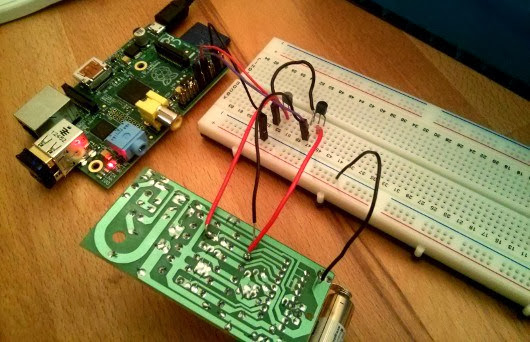
A 555-Based, Two-Channel Remote Control Circuit

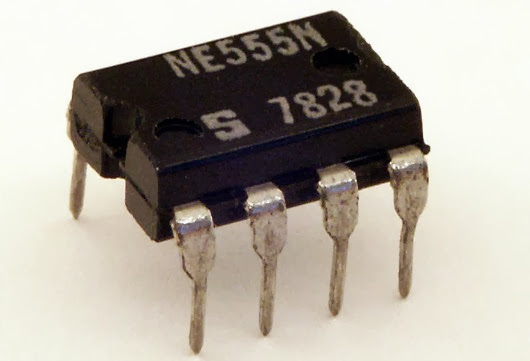
[fahadshihab], a young tinkerer, shared his circuit design for a simple remote control using 555 timers.  Using a 555 calculator, he designed a clock circuit that would run at 11.99 Hz. Two transistors are connected to inputs (presumably button switches). One sends the plain clock signal, and one sends the inverted clock signal. A matching circuit at the other end will separate the channels. All it requires is connecting the two circuits in order to synchronize them. It would be easy enough to interface this with an oscillator, an IR LED, or a laser for long-range control.
A 555-Based, Two-Channel Remote Control Circuit
The great thing about this circuit is its simplicity. It’s often so easy to throw a microcontroller into the mix, that we forget how effective a setup like this can be. It could also be a great starter circuit for a kid’s workshop, demonstrating basic circuits, timers, and even a NOT gate. Of course, it would be a good refresher for those without a lot of circuit knowledge too. Once you’ve mastered this, perhaps an AM transmitter is next?
read the rest of article...

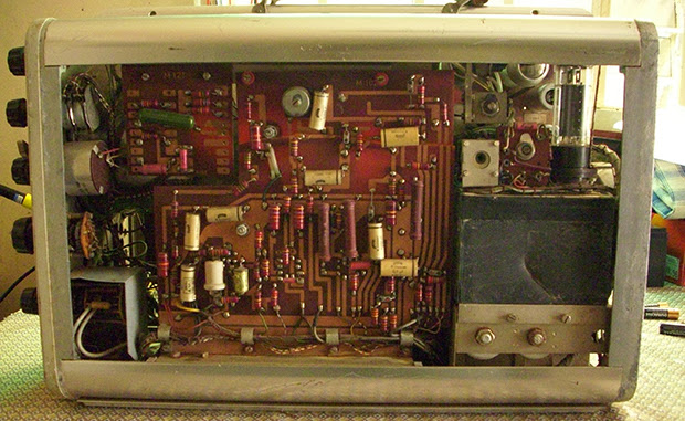
Tearing Down an Ultrasound Machine From 1963

Vintage electronics are awesome, and old medical devices doubly so. When [Murtaugh] got his hands on an old ultrasound machine, he knew he had to tear it apart. Even if he wasn’t able to bring it back to a functional state, the components inside make for great history lesson fifty years after being manufactured.
Tearing down an ultrasound machine from 1963
This very primitive ultrasound machine was sold by Siemens beginning in 1963 as a, “diagnostic ultrasound unit for the quick evaluation of cerebral hemorrhage after accidents.” This is barely into the era of transistors and judging from [Murtaugh]‘s teardown, nearly the entire device is made of vacuum tubes, capacitors, and resistors. The only solid state component in this piece of equipment is a bridge rectifier found in the power supply. Impressive stuff, even today.

In the end, [Murtaugh] decided this device wasn’t worth repairing. There were cracks all the way through a PCB, and he didn’t have any of the strange proprietary accessories anyway. Still, this junkyard score netted [Murtaugh] a bunch of old tubes and other components, as well as a nifty CRT that came with a wonderful ‘Made in West Germany’ label,.
read the rest of article...

Hacking Coin Collection

Devices that collect coins for payment typically use standardized coin acceptors like the one shown here. These devices use a protocol called ccTalk to let the system know what coins were inserted. [Balda] has built tools for implementing the ccTalk protocol to let you play around with the devices. He also gave a talk at DEF CON (PDF) about the protocol.
Hacking Coin Collection
[Balda] got started with ccTalk because he wanted to add a coin acceptor to a MAME cabinet, and had a coin acceptor. His latest project converts ccTalk to standard keyboard keystrokes using a Teensy. The MAME cabinet can then interpret these and add to the player’s credits.
There’s two interesting sides to this project. By providing tools to work with ccTalk, it’s much easier to take a used coin acceptor off eBay and integrate it into your own projects. On the other hand, these acceptors are used everywhere, and the tools could allow you to spoof coins, or even change settings on the acceptor.
read the rest of article...

Crafting A Liquid Crystal Display

Throughout the 1960s, the management at RCA thought LCD displays were too difficult to commercialize and sent their engineers and researchers involved in LCDs off into the hinterlands. After watching [Ben Krasnow]‘s efforts to build a liquid crystal display, we can easily see why the suits thought what they did. It’s an amazing engineering feat.
Crafting A Liquid Crystal Display
Before building his own version of an LCD (seen above in action), he goes through the mechanics of how LCDs operate. Light enters the display, goes through a polarizer, and is twisted by a liquid crystal material. The first successful LCDs used two types of liquid crystals – chiral and nematic. By combining these two types of molecules in the right proportion, the display can ‘twist’ the polarized light exactly 90 degrees so it is blocked by the second piece of polarizing film in the display.

Besides getting the right crystals and engineering processes, another major hurdle for the development of LCDs displays is transparent electrically conductive traces. [Ben], along with every other LCD manufacturer, uses a thin layer of indium tin oxide, or ITO. By embedding these clear electrodes in the display, segments can be built up, like the seven segment displays of a calculator or a bunch of tiny dots as found in a TV or computer monitor.

In the end, [Ben] was able to build an extremely simple single-segment LCD display out of a pair of microscope slides. It does modulate light, just barely. With a lot of work it could be made in to a calculator type display but for now it’s an awesome demonstration of how LCDs actually work. http://www.youtube.com/watch?v=d4QFNWBSZYg
read the rest of article...

The Atari Jaguar That Should Have Been

Released in 1993, the Atari Jaguar suffered from a number of problems – it was difficult to program, had hardware idiosyncrasies, and with the CD drive was vastly overpriced compared to the Sega Saturn and Sony Playstation released one year later. Nevertheless, the Jaguar still has a rabid fanbase that counts [10p6] among them, and he’s created what Atari should have released 20 years ago.
The Atari Jaguar That Should Have Been
In a few forum threads at jaguarsector (login required) and nexgam.de (no login, German), [10p6] goes over his changes to the classic Jaguar + CD combo. He’s stuffed everything inside a new case, cutting down on the amount of plastic from the old enclosure. A proper integrated power supply has been added, replacing the two power supplies used in the original. It’s also overclocked to 32 MHz, compared to the 26 MHz of the stock unit, making this a very powerful system that could have easily competed with the Saturn and Playstation.
[10p6] has an amazing piece of hardware on his hands here, and should he ever want to make a few molds of his new Jaguar, he could put together some sort of kit to replicate this build. He’s still working on finding a model maker and perfecting his case design, but a new, improved version of the Jaguar is something we’d love to see in a limited production.
read the rest of article...

Amateur Radio Transmits 1000 Miles On Voice Power

Many of us tried the old “Two tin cans connected by a string” experiment as kids. [Michael Rainey, AA1TJ] never quite forgot it.  Back in 2009, he built “El Silbo”, a ham radio transmitter powered entirely by his voice. El Silbo is a Double Side Band (DSB) transmitter for 75 meters. While voice is used to excite the transmitter, it doesn’t actually transmit voice.
Amateur Radio Transmits 1000 Miles On Voice Power
El Silbo is a CW affair, so you should bone up on your Morse Code a bit before building one. Like many QRP transmitters El Silbo’s circuit is rather simple. A junk box loudspeaker is installed at the bottom of the can to convert voice power to electrical power. The signal is passed through a step up transformer, and used to excite a 75m crystal. Two NPN transistors (in this case MPS6521) pass the signal on through a second transformer. The signal is then routed through an LC network to the antenna.


Back in 2009, [Michael] brought El Silbo to the Maine coast in an attempt to make a transatlantic contact. This isn’t as far-fetched as it sounds – [Michael] has “crossed the pond” on less power. While the attempt wasn’t successful, [Michael] has made connections as far as 1486km, or 923 miles.

That’s quite a distance for simply yelling into a tin can! One of [Michael's] favorite El Silbo stories is a 109KM conversation (QSO) he had with W1PID. [Michael] found that the signal was so good, he didn’t have to yell at all.

He reduced power by dropping to his normal speaking voice for the “dits and dahs”. The two were able to converse for 17 minutes with [Michael] only using his speaking voice for power. We think this is an amazing achievement, and once more proof that you don’t need a multi-thousand dollar shack to make contacts as a ham.
read the rest of article...

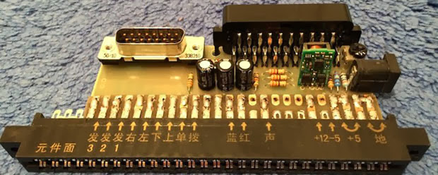
Mini Supergun PCB

A few decades ago, Japanese manufacturers of arcade games realized they should make a connector for all their boards that provides the power, controller, video, and audio I/O. This became the JAMMA standard and it make arcade owner’s lives awesome. Because you can buy arcade boards off the Internet, arcade enthusiasts figured out they could build their own console with an ATX power supply, AV connectors, and a few controllers.
Mini Supergun PCB
These ‘superguns’ as they’re called are big devices with wires all over the place. [Charlie] wanted to condense the size of his supergun and ended up creating a single PCB solution.

The JAMMA compatable boards require a few power connections; +5 V, +12 V, and -5 V. Of all the boards [Charlie] has collected so far, he realized only one used the negative supply. This, along with a big 12V laptop power supply, means the only power connection for this mini supergun is a single barrel connector.

For the controls and A/V, DSub and SCART connectors are commonplace. Laying these parts out in Eagle resulted in a single-sided board that is easily fabbed by etching with a toner transfer at home.

There are a few problems with the build, as [Charlie] admits. Some of the pins on the JAMMA connector aren’t on the board. These are only ground pins on the pinout, and so far everything works okay. It’s still a great project, though, that turns old arcade boards into a playable device with a minimal amount of hardware.
read the rest of article...

The Nibbler: a 4-bit CPU built with 7400 logic

Maybe we shouldn’t say “built” since [Steve Chamberlin] hasn’t actually heated up his iron yet. From the finished schematic above that is puzzling at first, until you realize the scope of the project. His Nibbler implements a 4-bit CPU using 7400 logic chips. Because he’s come up with the architecture himself he’s taking a lot of steps to check all of his work before committing to a PCB.
The Nibbler: a 4-bit CPU built with 7400 logic
We linked to his category for the project which is still in progress. Most recently he wrote a program to prove that it’ll run on the hardware. That’s a feat considering this is still just a design idea. It was made possible because he wrote a simulator based on the design. The C++ tool simulates data and control buses and features a full set of debugging tools.

Careful testing of the design before the build is the best possible way to go. The simulator and debugging tools will be useful for software development even after the hardware is built. And testing before wiring is a must as these things get out of control quickly in terms of soldering complexity.
[via Dangerous Prototypes]
read the rest of article...