Repairing and Adding Bluetooth Control to an Induction Cooker

When his 6 years old induction cooker recently broke, [Johannes] decided to open it in an attempt to give it another life. Not only did he succeed, but he also added Bluetooth connectivity to the cooker. The repair part was actually pretty straight forward, as in most cases the IGBTs and rectifiers are the first components to break due to stress imposed on them. Following advice from a Swedish forum, [Johannes] just had to measure the resistance of these components to discover that the broken ones were behaving like open circuits.
Repairing and Adding Bluetooth Control to an Induction Cooker
He then started to reverse engineer the boards present in the cooker, more particularly the link between the ‘keyboards’ and the main microcontroller (an ATMEGA32L) in charge of commanding the power boards. With a Bus Pirate, [Johannes] had a look at the UART protocol that was used but it seems it was a bit too complex. He then opted for an IOIO and a few transistors to emulate key presses, allowing him to use his phone to control the cooker (via USB or BT). While he was at it, he even added a temperature sensor.
read the rest of article...

Hacking a Mac Magsafe Jack into a PC Ultrabook

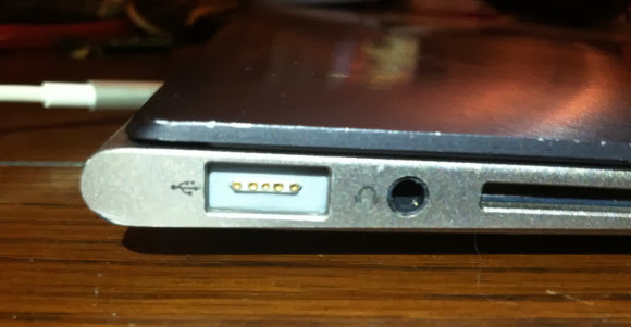
Something’s fishy about the above-pictured ultrabook: it’s an Asus Zenbook that [WarriorRocker] hacked to use a MagSafe power connector typically found on Macbooks. Most of us probably consider it standard procedure to poke around inside our desktop’s tower, but it takes some guts to radically alter such a shiny new ultrabook. It seems, however, that the Zenbook’s tiny power plug causes serious frustrations, and [WarriorRocker] was tired of dealing with them.
Hacking a Mac Magsafe Jack into a PC Ultrabook
Using information he found from an article we featured earlier this summer on a MagSafe teardown, [WarriorRocker] hit up the parts drawer for some connectors and got to work. He had to modify the MagSafe’s housing to fit his Zenbook while still holding on to the magnets, but he managed to avoid modifying the ultrabook’s case—the connector is approximately the same size as a USB port.

Deciding he could live with just one USB connection, [WarriorRocker] took to the board with a pair of side cutters and neatly carved out space for the MagSafe next to the audio jack. He then soldered it in place and ran wires from the VCC and Ground pins along a the channel where the WiFi antenna is routed, connecting them to the original power jack’s input pins.

[WarriorRocker] regrets that he fell short of his original goal of getting the MagSafe’s protocol working: he instead had to hack on his own adapter. We’re still rather impressed with how well his hack turned out, and it did manage to solve the charging problems. Hit us up in the comments if you can provide some insight into the MagSafe’s otherwise obscure innerworkings.
read the rest of article...

Solder Sucker Meets Industrial Vacuum Pump

[borgartank] is starting a hackerspace with a few guys, and being the resident electronics guru, the task of setting up a half-decent electronics lab fell on his shoulders.
Solder Sucker Meets Industrial Vacuum Pump
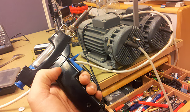
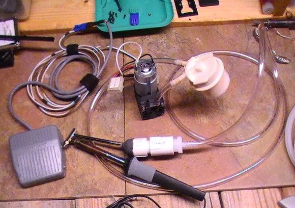
They already have a few soldering stations, but [borgar] is addicted to the awesome vacuum desolderers he has at his job. Luckily, [bogar]‘s employer is keen to donate one of these vacuum desolderers, a very old model that has been sitting in a junk pile since before he arrived. The pump was shot, but no matter; it’s nothing a few modifications can’t fix.

The vacuum pump in the old desoldering station was completely broken, and word around the workplace is the old unit didn’t work quite well when it was new. After finding a 350 Watt vacuum pump – again, in the company junk pile – [bogar] hooked it up to the old soldering station. Everything worked like a charm.

After bolting the new and outrageously large pump to the back of the desoldering station, [bogar] wired up a relay to turn on the pump with the station’s 24V line. Everything worked as planned, netting the new hackerspace a 18 kg soldering station.
read the rest of article...

DVD Power Supply Repair Tips

This demonstration fixes the power supply of a DVD player, but the skills transcend this one application. [Alan] walks us through the process of repairing a power supply (translated) on a simple consumer electronics unit.
DVD power supply repair tips
Obviously this starts by cracking open the dead device and verifying that the culprit is the power supply. [Alan] then removes that board from the chassis and gets down to work with a visual inspection. He’s got several images which illustrate things to look for; blistered electrolytic capacitors, cracked solder joins, scorch marks, etc. In his case there’s obviously a burnt out fuse, but that merely protects the hardware from further damage, it’s not the cause. Next he examines the diodes of the bridge rectifier. These need to be removed from the system to do so, which he accomplishes by clipping one end of each as seen above. He found that two diodes on one side of the bridge had broken down. After replacing them he tries a new fuse which immediately burns out. But a quick swap of the capacitors and he gets the thing back up and running.
read the rest of article...

Apple MagSafe cord repair

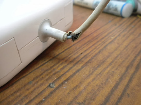
[Tommy Ward] had a big problem with the cord for his laptop power supply. This thing’s not cheap so he figured out a way to fix the frayed cord on his Apple MagSafe. He asserts that the shortened rubber collar on the plug end of the cord is to blame for this type of damage. We think rough use may have something to do with it too, but having had to repair our own feline-damaged power cords we’re not about to start pointing fingers.
Apple MagSafe cord repair
To pull off an appropriate fix [Tommy] pries apart the case housing the power converter. This lets him get at the solder connections of the cord. After removing it from the circuit board he clips off the damaged portion of the cable. To reuse the strain relief grommet he drilled out the old portion of wire and insulation, making room for the undamaged cable to pass through, adding a cable tie on the inside to aide in strain relief. The last part of the fix involves gluing everything back together.
read the rest of article...

Laptop Backlight Converted From CCFL to LED

[Lee Davison] acquired an Acer laptop that didn’t have a display anymore. He had enough parts on hand to add in an LCD panel and give it a CCFL backlight. But when he started looking for an inverter to drive the backlight he couldn’t find one. What he did have on hand were some smashed screens that had LED backlights and so the CCFL to LED backlight conversion project was born.
Laptop backlight converted from CCFL to LED
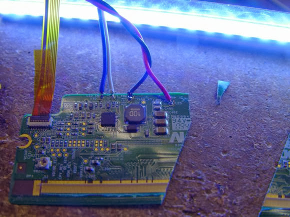
He tore into the LED display and found the driver board. Unfortunately he didn’t locate the datasheet for the exact LED driver, but he found one that was similar and was able to trace out the support circuitry on the PCB. This let him cut away the unneeded parts of the board without damaging the driver. He didn’t want to pull out the CCFL tubes until he was sure the LED conversion would work so he tried it out on another smashed panel (where does he come up with all these parts) and it worked great. Once he got everything in place he was very happy with the results. The only drawback to the system is that he doesn’t have the ability to dim the backlight.
read the rest of article...

The trials of repairing a MacBook

As a favor to a friend, [Phil] traded a unibody MacBook logic board for one with a broken headphone jack, a busted keyboard controller, and a nonfunctional fan. Not one to let bad hardware go to waste, he set off to repair this now-broken laptop by scavenging parts wherever he could. The whole thing ended up working, and became a very impressive display of soldering skill in the process.
The trials of repairing a MacBook
The first step for the keyboard transplant was to cut a properly sized hole in the newer unibody MacBook for an older, pre-unibody MacBook Pro 17″ keyboard. This was done by cutting out the keyboard pan of the pre-unibody case and very carefully epoxying it into the unibody chassis. The MBP had a separate keyboard and trackpad controller, so of course [Paul] needed to find some space inside the chassis for these new electronics. This space was found next to the internal hard drive, and a liberal application of hot glue held everything together.
In the future, [Phil] plans on adding more LEDs, a 3.5 mm jack, and a USB to TTL converter – a necessity for any true ‘hacker’ laptop. It’s still a wonderful piece of work, and an incredible amount of effort and skill to get it where it is today.
read the rest of article...

Vaporizer Rebuild

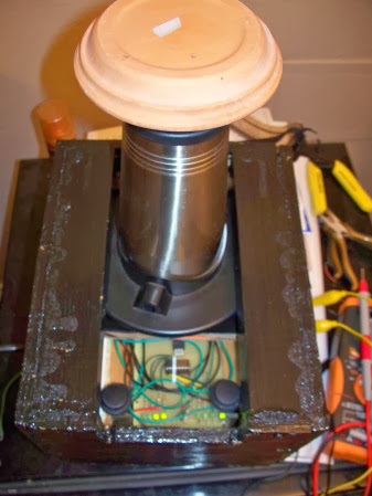
Wait! Don’t click away yet. Yes, this is a vaporizer project, but it has the distinction of being the most electronics engineering oriented post on the subject we’ve ever featured. [Mm Nn's] vaporizer broke so he decided to fix it. After poking around inside it became clear that pretty much everything was trashed. So this ended up being a complete rebuild of all the support circuitry, with the heating element being the only electrical component he could salvage.
Vaporizer rebuild
He started looking around for a power supply capable of driving the element from the Arizer V-tower vaporizer. He hoped that he could use a computer PSU but ended up having to buy one to suit; a Mean Well rs-100-24. He drives the system with a microcontroller (programmed in assembly) using PWM to adjust the element. Speaking of, there is a sensor built into the heating element that [Mm] isn’t using because he couldn’t figure out how to read from it. If you’ve got some ideas let us know in the comments.
read the rest of article...

Repairing a Mill That Cost as Much as a Car

Years ago, someone at the bio-instrumentation lab at MIT needed to change a CMOS battery in the controller for a three axis mill. This reset the machine’s BIOS and was widely regarded as a bad move. The mill sat in the lab for a few years before  Prof. [Ian Hunter] donated it to MITERS – the student shop at MIT. And so the task of repairing a machine that cost as much as a car fell upon a plucky group of students.
Repairing a mill that cost as much as a car
The machine – a  Dyna-Myte 1007 has a 10″x7″x10″ work area, pneumatic tool changers and carousel, and the working for a fourth axis. It is. however, driven by an ancient Pentium computer running DOS with all the fun of ISA slots and IRQs that entails.

The MITERS began their repair by digging around in the software configuration, finding the axis drive is controlled via IRQ 3, which was currently occupied by COM 2. Changing that in the BIOS let the computer control the axes and, with a few solenoids and an air compressor, the tool carousel also worked.
With a bit of digging around, the MITERS also got the spindle working, giving them a very awesome and very expensive CNC milling machine for free. Even though the computer could be replaced with a $35 Raspberry Pi, we really have to admire the MITERS for fixing what they already had; it’s a cheaper and much, much faster way to get their new toy up and running.
read the rest of article...

Build Your Own Desoldering Station on the Cheap

Sable Wolf] tipped us off to his DYI desoldering station for under $70. We know we have seen this conversion before, but it hasn’t been featured on Hack a Day. [Sable Wolf’s] hack is unique and has added features that make building, cleaning and the overall longevity sounder. However, some kind of sound deadening housing would have to be built around the pump as it seemed uncomfortably loud in the video.
Build Your Own Desoldering Station on the Cheap
Some Chinese made desoldering stations are getting quite cheap so maybe it’s not worth the effort unless you can salvage more components for the build. Thanks to [Sable Wolf’s] detailed blog you can browse through his BOM and scrounge up the majority of these items from your salvage bins. A cheap but reliable desoldering station would be an extremely handy tool to have on your bench.
This is much safer than desoldering with a candle or using fire as featured in the past, and is kind of a flip around on the SMD hot air pencil hack.
Follow long after the break to watch the video of the desoldering station in action.
read the rest of article...

Diagnose and Repair a Yaesu FT-7800 Ham Radio

[Alan Wolke] aka [w2aew] was challenged to repair a friends Yaesu FT-7800 ham radio. This radio operates on two ham bands, 2 m VHF and 70 cm UHF. The complaint was that the 2 m side was not working but the 70 cm was transmitting fine. Alan started by verifying the complaint using a Bird watt meter with a 50 watt slug and terminating the signal into a 50 W dummy load. [Allen’s] bird meter is the type that has an RF sampler that can be connected to an oscilloscope for added signal viewing and validation.
Diagnose and Repair a Yaesu FT-7800 Ham Radio
After verifying that the radio was not working as described, Alan starts by glancing over the circuit board to look for any obvious damage. He then walks us through a block diagram as well as a circuit diagram of the FT-7800 radio before stepping us through the troubleshooting and diagnostics of radio repair. Even when he realizes he might have found the problem he still steps us through the remainder of his diagnostics. The skills and knowledge that Alan shares is extremely valuable to anybody looking to repair radios.


Spoiler alert. At the end of the first video he determines that the pin diodes near the final VHF output were bad. In the second video he reveals that he could no longer source these bad components. Through some clever evaluation of a more current Yaesu radio, [Allen] was able to find suitable replacement components. Lesson two ends with some surface mount solder rework tips as well as testing that the repair was successful.


And just in case you don’t know what a pin diode is, or is used for, Alan shares a third video covering just what this component is and does in a radio. You can follow the jump to watch all three videos.

read the rest of article...