Case Modder Builds LCD Window; Causes LSD Flashbacks

[Chris, aka Mosquito's Mods]  is well-known for some awesome PC case mods. He’s outdone himself this time with an embedded LCD panel as his case window. This use of an LCD is becoming common on arcade games and slot machines. [Chris] was inspired by an arcade game he saw at a local Dave & Buster’s. He started with an off the shelf 16″ USB LCD monitor from AOC.Case Modder Builds LCD Window; Causes LSD Flashbacks

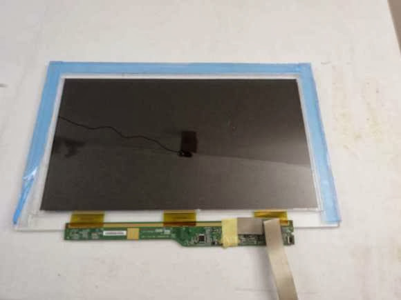
[Chris] then stripped off the back light, diffuser, and reflectors. Left with  the bare panel and polarizers, he then created an LCD sandwich of sorts. First a layer of 2mm acrylic. Then the LCD and panel, along with 4 strips of acrylic forming a frame around the LCD. The frame strips are in blue in the image after the break.
Case Modder Builds LCD Window; Causes LSD Flashbacks
 The final layer is a thick piece of 6mm acrylic. The thick acrylic keeps the window assembly from bending, which would lead to a cracked LCD. The entire assembly is held together with 3M scotch 4010 tape. White LED strips around the LCD shine plenty of light into the case, allowing the images on the LCD to be seen. The final effect is stunning. Images on the LCD appear to be floating in space somewhere behind the window. The effect works best with back and white images, as color is understandably a bit washed out.
read the rest of article...

Re-purposing an Old Laptop Display

[Tim] found himself with a laptop that had a good 18.4″ screen, but otherwise didn’t run properly. It would be a shame to throw that away, so he decided to salvage the screen by turning it into a standalone monitor. This isn’t exactly new, as he did what many people have done and looked to eBay for an after-market LCD controller board.
Re-purposing an Old Laptop Display
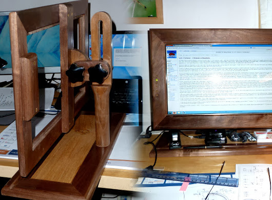
The real beauty is in the enclosure he built. [Tim] had some scrap wood available from a previous project, so he set about designing a new frame for the monitor, and a very nice adjustable stand, as can be seen in the photo above. One nice detail is in the control panel buttons. The LCD controller comes with a separate board housing the controls, and while he made a mistake mounting it initially, he ended up with a nice set of oak buttons that match the frame perfectly.

He then built a nice backing out of styrene that holds the screen in place as well as housing the electronics. Overall, it’s a nice looking project, and it is always nice to see electronics re-purposed rather than ending up in a landfill. We can’t help but think this would be a great frame for building a picture frame or a wall-mounted PC as well.
read the rest of article...

VT100 Gets BeagleBoned

How do you make a great terminal even better?  The answer is simple: add a BeagleBone Black to it! [Brendan] got his hands on one of the staples of classic computing, the DEC VT100 terminal.  The VT100 was produced from 1978 to 1983. The terminal was so widely used that it became the standard for other terminals to emulate. Open any terminal program today and chances are you’ll find a setting for VT100 emulation.
VT100 Gets BeagleBoned
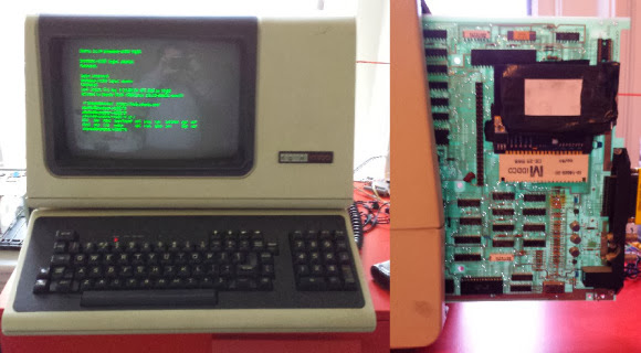
[Brendan] originally hooked his terminal up to a laptop running Linux. The terminal, cables, and the laptop itself became quite a bit to manage on a small desk. To combat this he decided to add a BeagleBone Black inside the terminal case. It turns out the VT100 actually lends itself to this with its Standard Terminal Port (STP) connector. The STP was designed to add a “paddle board” in-line with the serial stream of the terminal. DEC and third party manufacturers used this port to add everything from disk drives to entire CPM computers to the VT100.

[Brendan] began by designing a board to interface between the VT100 and the BeagleBone. The board level shifts serial lines from the BeagleBone to the VT100. The STP also allows the terminal to provide power to the BeagleBone Black.  He did notice some power glitches as the supply of the VT100 came up. This was solved with a standard TI TL77xx voltage supervisor chip. The hardest part of the entire design was the card edge connector for the STP. [Brendan] nailed the dimensions on the first try.In the end [Brendan] was rewarded with a very clean installation that didn’t require any modification to a classic piece of hardware.

We should note that most PCB houses use Electroless Nickel Immersion Gold (ENIG) as their standard coating. This will work for a card edge connector that will be plugged in and removed a few times.  Cards that will be inserted and removed often (such as classic console cartridges) will quickly scrape the ENIG coating off. Electroplated Gold over Nickel is the classically accepted material for card edge connectors, however the process most likely is not going to come cheap in hobbyist quantities.
read the rest of article...

Turn a PC on with a Knock and an ATTiny

Pressing the power button on your computer usually isn’t too much trouble, unless your computer is stored away somewhere hard to reach. [Joonas] has been hard at work on a solution that would also impress his friends, building a knock sensor to turn on his PC.
Turn a PC on with a Knock and an ATTiny
For around $10 in parts he put together an ATTiny45 that emulates a PS/2 device, which takes advantage of his computer’s ability to boot upon receiving PS/2 input. The build uses a Piezo buzzer and a 1M Ohm resistor as a knock sensor exactly as the official Arduino tutorial demonstrates, and one of those PS/2-to-USB adapters that are most likely lurking in the back corner of every drawer in your office.

[Joonas] used AVRweb to disable the 8X clock divider so there’d be enough clock cycles for PS/2 communication, then loaded some test code to make sure the vibrations were being detected correctly. You can check out his Github for the final code here, and stick around after the break for a quick video demo. Then check out a similar hack with [Mathieu's] home automation knock sensor.


https://www.youtube.com/watch?v=FTVppOZquE8
read the rest of article...

ASAP 3 – The Almost Simple As Possible Computer

[Pong] has joined an elite club of people who have designed and built their own computer – including a CPU created from discrete 7400 series logic. His computer is the  Almost Simple As Possible Computer 3 (ASAP-3). ASAP-3 is not a completely new design.
ASAP 3 – The Almost Simple As Possible Computer
The architecture is based upon the SAP series of computers from Albert Malvino’s book, Digital Computer Electronics. [Pong] looked at quite a few of the “modern retro” computers such as Magic-1, Big Mess o’ Wires 1, and the Duo. These computers were beyond his skill levels back then, so he began to build his own system. His primary design goal was to be able to run a 4 function calculator program.


One thing that can’t be stressed enough is the fact that [Pong] made his design work much easier by using lots of simulation. His tool of choice was Proteus Design Suite. While simulation can’t solve every problem, it can often help in verifying that a given design is sound. The ASAP-3′s instruction set is microcode, based upon the 8085 series instruction set. The microcode itself is stored on Flash ROMS. Using microcode makes ASAP-3 very flexible. Don’t have a machine instruction you need? No problem – just write one up. When all was said and done, [Pong] had over 100 instructions spread over 3 Flash ROM chips.

The hardware was only half the battle – [Pong] found writing the software just as challenging. He wrote all the software by hand in his own machine code. This is where the simulation mentioned above really saved him some time. Even with simulation he still ran into some problems. The ASAP-1 is limited to a clock speed of around 500kHz. Above that, glitches from the ROM chips start triggering the asynchronous inputs in some of the registers.

[Pong] doesn’t have a logic analyzer on hand, so he wasn’t able to track this one down further. He also found a (update simulation only) issue with the carry bit on the 74LS181 bit slice ALU. In certain circumstances the carry bit would not propagate correctly. [Pong] corrected this by using a ROM as a look up table replacement for certain ’181 functions. Even with these limitations, this is still a great hack!
read the rest of article...

Battery Backup for RasPi Keeps Your Data Safe

We’ve all raised a clench fist in anger over lost data, and it’s usually the result of unjustified optimism and lack of planning. [George] shared his solution that prepares for the worst: a circuit that provides backup power to a RasPi and its hard drives. [George's] Pi setup runs as both an Apple Time Machine server and a website backup server, and a power outage could corrupt the data stored on the Pi’s attached hard drives.
Battery Backup for RasPi Keeps Your Data Safe
Rather than turn to commercial solutions, however, [George] wanted to take advantage of the Pi’s low power consumption and create an inexpensive custom circuit that would safely and automatically power down the devices upon loss of power. To detect a power failure, the build connects one of the Pi’s GPIOs to an opto-isolator, which—through a zener diode—connects to the 12V wall adapter: though [George] welcomes suggestions for alternative methods of safely identifying a mains power loss.

The rest of the circuit serves as a trickle charger for the two attached 9V batteries and as a regulator to supply the correct voltage to the RasPi. Power MOSFETs connected to a GPIO handle the delayed power off. You can view (and edit!) the circuit online here and find the relevant source code on [George's] website.
read the rest of article...