Retrotechtacular: Tube Amplifiers

It’s hard to beat this vintage reel for learning about how vacuum tube amplifiers work. It was put together by the US Army in 1963 (if we’re reading the MCMLXIII in the title slide correctly). If you have a basic understanding of electronics you’ll appreciate at least the first half of the video, but even the most learned of radio enthusiasts will find something of interest as they make their way through the 30-minute presentation.
Retrotechtacular: Tube Amplifiers
The instruction begins with a description of how a carbon microphone works, how that is fed to a transformer, and then into the amplifier. The first stage of the tube amp is a voltage amplifier and you’ll get a very thorough demo of the input voltage swing and how that affects the output. We really like it that the reel discusses getting data from the tube manual, but also shows how to measure cut-off and saturation voltage for yourself. From there it’s off to the races with the different tube applications used to make class A, B, and C amplifiers. This quickly moves onto a discussion of the pros and cons of each amplifier type.See for yourself after the jump.
read the rest of article...

Bizarre Mini Amplifier + White Noise Generator?

[Jordi] made this awesome looking mini amplifier which has a rather unusual feature. He’s calling it the Bizarre Mini Amplifier because it also has a white noise generator built right into it! Bizarre right?
Now, most people would just find a suitable amplifier and put it into a nice box, but not [Jordi]! He’s designed the amplifier circuit from the ground up! It features four distinct stages like most typical amplifiers:
Bizarre Mini Amplifier + White Noise Generator?
  1. Impedance Adapt Stage: Two OPAMPS for both the left and right channels — The high input impedance allows for different audio sources to be connected without affecting the output.
  2. Mixer stage: Combines the left, right and noise signals into one, using a third OPAMP. A potentiometer is the output resistor which allows for the volume control.
  3. Filter Stage: A simple filter stage that uses a R-C low-pass filter, another potentiometer controls the tone.
  4. Power Stage: A final power amplifier to boost the output.
After building the circuit, there was a bit of troubleshooting to get it to work properly, so if you’re interested [Jordi] has done a great write-up of this on his blog.
Finally, he decided to add a white noise generator after he discovered it helps him sleep. This is the one part of the project that he didn’t actually go into detail for! But, considering it’s just white noise, we could probably figure out what he did. Stick around after the break to see the device in action!


There’s just something about the retro style look to this thing that we love. We know it’s just a plain old white project box, but between the clear speaker, chrome switches and old labels, it just looks… great!
read the rest of article...

Fubarino Contest: Morse Code Transmitter

The Fubarino Contest entries are slowing streaming in. Here’s the first one that we’re featuring, sent in by [Nathanael Wilson]. He dusted off a project from some time ago, which is just fine with us. It’s a Morse Code transmitter which he designed for use during a fox hunt (locating a hidden transmitter using radio direction finding).
Fubarino Contest: Morse Code Transmitter
For the project he revised his old code, adding in a Morse look-up table so that the Arduino Mega 2560 can convert plain text into dots and dashes. It uses the tone library to output signals to the radio seem above. The easter egg is unlocked when shorting pin 10 at power-up. It then broadcasts a slightly altered message as interpreted above.


One of the reasons we chose to feature [Nathanael's] entry first is that he presented it very well. Watch his video after the break to see for yourself. Then go back and check out the contest rules to get your own project submission in. After all, you can win a free Fubarino board from Microchip if you’re in the top twenty!
read the rest of article...

Sniffing Data from Radio-Controlled Bus Stop Displays

A few weeks ago in Finland [Oona] discovered a radio data stream centered around 76KHz in a FM broadcast and she recently managed to decode it. This 16,000bps stream uses level-controlled minimum-shift keying (L-MSK) which detection can be quite tricky to implement. She therefore decoded the stream by treating the received signal as non-coherent binary FSK, which as a side effect increased the bit error probability. [Oona] then understood that the stream she was getting was the data broadcast by Helsinky buses to the nearby bus stop timetable displays.
Sniffing Data from Radio-Controlled Bus Stop Displays
She even got lucky when she observed a display stuck in the middle of its bootup sequence, displaying a version string. This revealed that the system is called IBus and made by the Swedish company Axentia. However their website didn’t provide the specs for their proprietary protocol. After many hours of sniffing and coding, [Oona] successfully implemented the five layer protocol stack in Perl and can now read the arrival times of the nearby buses from her apartment.
read the rest of article...

Retrotechtacular: WWII Paraset Spy Radio Used by French Resistance

[Robert Sumption] a.k.a [W9RAS] takes on the daunting challenge of building a WWII spy radio called the Paraset as the topic of this week’s Retrotechtacular. It was originally a tube based CW (Morse code) transmitter/receiver used by the French underground to communicate with the Allies. Many of these radios were dropped behind enemy lines and could run on European AC or 6 V DC with the added advantage of being able to use most anything for an antenna, including fence wire.
Retrotechtacular: WWII Paraset Spy Radio Used by French Resistance
These small, low power and highly mobile radios tuned in the 3 to 8 MHz range were instrumental in the resistance. But they still make for a really fun scratch-built radio project.Hobby groups still build this brilliant little radio and use it regularly to make contacts at great distances using the 40 and 80 meter ham bands. This may not be a weekend project for everyone because you need to work with vacuum tubes and build a 400 V power supply to operate this type of radio.

Plus, sourcing some of the old components in working order is sometimes near impossible. [Bob] circumvents some of the problems by altering the design to marry up with his surplus supply of radio bits and bobs such as tubes (a.k.a. valves) and FT243 crystals he had on hand. And don’t forget, just as [Bob] says in his 5 part build video seen after the break; “Every day is a Hamfest on eBay”. So getting some of these parts, if not a partial-intact original Pareset radio, is always possible. If you search on the Internet for “PARASET RADIO” you will find other home-built examples with circuit diagrams and plenty of advice such as found on W7OIL.com and SHAW.ca.

part 1


part 2


part 3


part 4


part 5


read the rest of article...

555 Based AM Radio Transmitter

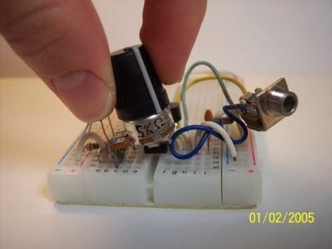
Bust out that 555 timer and use it to build your own AM radio transmitter. The circuit that [Rtty21] is using only needs the timer chip, an NPN transistor, three caps, three resistors, and a potentiometer. It generates an amplitude modulation signal around the 600 kHz range which you will be able to pick up with any normal AM radio.
555 based AM radio transmitter
From the comments on the article it seems you’ll get around 30-40 feet of range out of the device. We don’t see this as a competitor for the FM spy microphone, but maybe you can use it as a diy baby monitor.
read the rest of article...