Interfacing with the HTC Desire Display and its Touch Panel

Part of [Linas]‘ submission to last year’s Cypress Smarter Life Challenge involved using the HTC Desire display and its touch screen. This particular phone includes a full-color active-matrix OLED (AMOLED) display that has a 3.7″ diagonal and a 480×800 resolution, resulting in a 252ppi pixel density. Using a MSO2024B oscilloscope, [Linas] originally started his adventure with the touchscreen by sniffing the I2C signals. As some math was required to extract the data, he later found the HTC Desire source code and included it on his STM32F429 (so much for reverse engineering!).
Interfacing with the HTC Desire Display and its Touch Panel
After spending many hours searching for the AMOLED display and controller datasheets, [Linas] resorted to pay a company to get the resources he needed. He produced a custom-made PCB to provide the display with the required voltages, as well as offering a 0.1″ connector to interface with it. A RGB565 interface is used to communicate with the screen so only 65k out of the 16 million colors are used. You may download all the program files and datasheets in [Linas] write-up.
read the rest of article...

Testing The Limits Of Home PCB Etching

[Quinn Dunki]‘s Veronica, a homebrew computer based on the 6502 CPU, is coming along quite nicely. She’s just finished the input board that gives Veronica inputs for a keyboard and two old Nintendo gamepads. [Quinn] is building this computer all by her lonesome, including etching all the PCBs. She’s gotten very, very good at etching her own boards, but this input board did inspire a few facepalming moments.
In an earlier post, [Quinn] went over her PCB etching capabilities. As demonstrated by the pic above, she’s able to print 16 mil traces with 5 mil separation. This is just about as good as you can get with homebrew PCBs, but it’s not without its problems.
Testing The Limits Of Home PCB Etching
[Quinn] is using a photographic process for her boards where two copies of a mask is printed on an acetate sheet, doubled up, and laid down on a pre-sensitized copper board. The requirement for two layers of toner was found by experience – with only one layer of toner blocking UV light, [Quinn] got some terrible pitting on her traces and ground planes.

Two photographic masks means the masks must be precisely aligned. This example shows what happens when the acetate sheets are ever so slightly misaligned. With a 5 mil gap between traces, [Quinn] needs to align the masks to within ±2.5 mils; difficult to do by eye, and very hard once you factor in flexing and clamping them down to the copper board.

Even when this process goes perfectly, [Quinn] is pushing the limits of a laser printer. When printing at 600 dpi, the pixels of the print are about 1.5 mils. While GIMP, printer drivers, and the printer itself have some fancy software to help with the interpolation, [Quinn] is still seeing ‘bumps’ on the edges of perfectly aligned parts. This is one of those things that really makes you step back and realize how amazing fabbing PCBs at home actually is. With most of the hardware for Veronica out of the way, it’s just about time for [Quinn] to start programming her baby. We’re not expecting a full-blown operating system and compiler, but those NES gamepads are probably crying out for some use.
read the rest of article...

A Low Cost Dual Discriminator Module for the Easy-phi Project

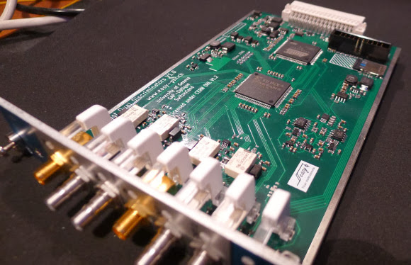
A few months ago I presented you the Easy-phi project, which aims at building a simple, cheap but intelligent rack-based open hardware/software platform for hobbyists. With easy-phi, you simply have a rack to which you add cards (like the one shown above) that perform the functions you want.
A Low Cost Dual Discriminator Module for the Easy-phi Project
Recently my team finished testing our FPGA-based discriminator or “universal input” if you prefer. As easy-phi cards use a well-defined electrical signal to communicate with each other, we needed to make a card that would translate the different kinds of electrical signals from the outside, as well as perform plenty of other functions. It was therefore designed to have a 100MHz input bandwidth with an AC/DC coupled 50 ohm/high impedance input stage (x2) and 4 easy-phi outputs.

For this module, we picked the (old) spartan3-an FPGA to perform the different logic functions that may be needed by the final users (high speed counter, OR/XOR/AND, pulse creation,…). Using the cortex-m3 microcontroller present on the board, it may be easily reconfigured at will. All design resources may be found on our Github, and you can always have a look at our official website.
read the rest of article...

Easy Multi-Touch Table

[2bigbros] put up an Instructable on his multi-touch table build. It’s a nice setup, using the typical frustrated total internal reflection method for touch sensing. Tinkerman’s Method was used for the screen itself, which involves rolling silicon onto vellum with a paint roller to improve the bond. [2bigbros] then built a nice aluminum and wooden frame for the whole thing. He’s light on some details, but most people with a basic understanding and Google will be able to figure it out.
Easy Multi-Touch Table
This is a very accessible project for most builders. If you’re interested in getting into it, there are plenty of projects to reference. We previously covered the basics, as well as a more involved build. We’ve even seen an interactive tower defense game using multi-touch. If you decide to build one of your own, don’t forget the excellent resource at TUIO for finding frameworks and example implementations.

[via Instructables]

read the rest of article...

Hacking SD Card & Flash Memory Controllers

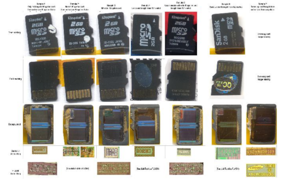
We hope that some of our readers are currently at this year’s Chaos Communication Congress (schedule can be found here and live streams here), as many interesting talks are happening. One of them addressed hacking the memory controllers embedded in all memory cards that you may have. As memory storage density increases, it’s more likely that some sectors inside the embedded flash are defective. Therefore, all manufacturers add a small microcontroller to their cards (along with extra memory) to invisibly ‘replace’ the defective sectors to the operating system.
Hacking SD Card & Flash Memory Controllers
[Bunnie] and [xobs] went around buying many different microSD cards in order to find a hackable one. In their talk at 30C3 (slides here), they reported their findings on a particular microcontroller brand, Appotech, and its AX211/AX215. By reverse engineering the firmware code they found online, they discovered a simple “knock” sequence transmitted over manufacturer-reserved commands that dropped the controller into a firmware loading mode.

From there, they were able to reverse engineer most of the 8051 microcontroller function-specific registers, allowing them to develop novel applications for it. Some of the initial work was done using a FPGA/i.MX6-based platform that the team developed named Novena, which we hope may be available for purchase some day. It was, among others, used to simulate the FLASH memory chip that the team had previously removed. A video of the talk is embedded below.

read the rest of article...

Testing Six Hundred Fish

That’s the best and most obtuse title you’ll ever see for a Hackaday post, but surprisingly it’s pretty accurate. [Bob] over at the Sector67 hackerspace took part in a 111-day accelerator program in Shenzhen last year to improve his manufacturing skills. He’s just about ready to release his first product, a Bluetooth device that connects to an ice fishing tip-up. The blog for the device recounts the challenges of taking a project from a circuit to a finished product, and illustrates the difference between building something with an Arduino and selling thousands of devices.
Testing Six Hundred Fish
The circuit boards for BlueTipz come in panels of eight, but what’s the best way to populate and solder five thousand devices in a reasonably short amount of time? [Bob] hired a few students from the local college to help him out in assembling all these devices. The plastic enclosures were made at a local plastics manufacturer, but the molds were made in China. The manufacturer needed to modify the molds a bit, but after a few days, [Bob] had five thousand enclosures ready to stuff full of electronics.

With the devices assembled, it’s time for programming, and that means building a programmer. [Bob] put all the guts for the device into a plastic box and 3D-printed a mount for the bare BlueTipz board. Put a board on the mount, press a button, and the tech now has a functioning device in his hands.

Besides manufacturing, there’s also a whole lot of testing that went into the design of BlueTipz. Because this is a device for ice fishing—a cold and potentially windy operating environment—[Bob] built a test rig in a freezer. The test rig triggers the device’s sensor, waits two minutes (the amount of time it would take for an ice fisherman to check the tip-up) and resets. They claim the battery life is good for 600 fish, and with this testing rig they were able to verify their calculated battery life with real-world data: without actually catching six hundred fish, of course.

Not only does [Bob] have a good bit of product development under his belt, he was also kind enough to go over the stuff everyday electronic design just doesn’t cover. Developing a product is something you can only learn by doing, and we’re glad [Bob] chose to share his experiences with us.
read the rest of article...

OpenMV: The Camera For Your Next Project

Last month we saw [Ibrahim] tackle the lack of cheap, high speed, high resolution serial cameras with full force. He designed a serial camera based on the STM32F4 microcontroller that’s the perfect solution to anyone wanting to add visual processing or machine vision to a project. It’s cheap, too: instead of the $100 or so you’d spend on a high-end serial camera, [Ibrahim]‘s version only has about $15 in parts.
OpenMV: The Camera For Your Next Project
Now he’s back at it again, with 25 FPS face detection, 30 FPS color detection, a new board with a micro SD socket, and support for USB OTG full speed. [Ibrahim] has been hard at work deep in the bowels of the STM32F4 micro, playing around with the core coupled memory. This allows for some very fast image processing, combined with the micro running at 168 MHz makes for very fast face and color detection.

As for a few benchmarks for this camera, the maximum resolution is 1280×1024, and at 88×72 resolution this little board can output at 60 FPS. Of course everything is limited by the speed of the serial connection, but there’s a lot of potential in this small serial camera. No word on how much this board will cost, but [Ibrahim] may be putting a few boards up on Tindie shortly. Here’s to hoping he’ll send us an email telling us when his store is open.
read the rest of article...

Using Ultrasonic Sensors to Measure and Log Oil Tank Levels

[Mike] lives in a temperate rainforest in Alaska (we figured from his website’s name) and uses a 570 gallon oil tank to supply his furnace. Until now, he had no way of knowing how much oil was left in the tank and what his daily usage was. As he didn’t find any commercial product that could do what he wanted, he designed his own solution. In his write-up, [Mike] started by listing all the different sensors he had considered to measure the oil level and finally opted for an ultrasonic sensor.
Using Ultrasonic Sensors to Measure and Log Oil Tank Levels
In his opinion, this kind of sensor is the best compromise between cost, ease of use, range and precision for his application. The precise chosen model was the ping))) bought from our favorite auction website for around $2.5. [Mike] built the custom enclosure that you can see in the picture above using PVC parts. Enclosed are the ultrasonic sensor, a temperature sensor and an LED indicating the power status. On the other side of the CAT5 cable can be found an Arduino compatible board with an XBee shield and a 9V battery. Using another XBee shield and its USB adapter board, [Mike] can now wirelessly access the tank oil level log from his computer.
read the rest of article...

Easy Capacitive Touch Sensors In Eagle

Capacitive sensing libraries for the Arduino and just about every other microcontroller platform have been around for ages now, but if you’d like to put a slightly complex cap sense pad in a PCB without a lot of work, you’re kind of out of luck. Not only do you need a proper education in how capacitors work, but a custom cap sense pad also requires some advanced knowledge of your preferred PCB layout program.
The folks over at PatternAgents have just the solution for this problem.
Easy Capacitive Touch Sensors In Eagle
They created an Eagle library of touch widgets that includes everything from buttons, linear and radial sliders, touchpads, and a whole lot more. The simplest cap sense pad is just a filled polygon on the top layer of a board, but this simple setup isn’t ideal if you want to use Eagle’s autorouter. By playing with the restrict layers in Eagle, PatternAgents were able to create easy cap sense buttons that will work perfectly, without the problems of the autorouter placing traces willy-nilly.

There are more than enough parts to replicate a whole lot of touch interfaces – buttons can easily be made into a smallish keyboard, and the radial touch sensor will emulate the ‘wheel’ interface on an iPod. Very cool stuff, and we can’t wait to see these in a few more boards.
read the rest of article...

DIY Thermal Imaging Camera

Thermal imaging cameras – those really useful devices that give you Predator vision – are incredible tools. If you’re looking for heat escaping your house through a window, or just trying to figure out where your electronics project will explode next, they’re invaluable, if expensive, tools. [Kaptein QK] figured out an easy and cheap way to make your own thermal imaging camera using nothing just a few dollars worth of parts.
DIY Thermal Imaging Camera
[Kaptein] based his camera off of a non-contact IR temperature gun. This device is useful for spot checking temperatures, but can’t produce an IR image like it’s $1000 cousins. By taking the thermopile out of this temperature gun, adding an op-amp, an A/D converter, and connecting it to an Arduino Nano with pan and tilt servos, [Kaptein] was able to slowly scan the thermopile over a scene and generate an image.


In the video below, you can see [Kaptein]‘s scanning camera in action reading the ambient temperature and creating an imaging program for his PC. It works very well, and there a lot more [Kaptein] can improve on this system; getting rid of the servos and moving to mirrors would hopefully speed everything up, and replacing the 8-bit grayscale display with colors would give a vastly improved dynamic range.
read the rest of article...

Building an Audio Box out of thrown Away boards

The last time [Mark] was at the scrap yard, he managed to find the analogue input and output cards of an old Akai DR8 studio hard drive recorder. These cards offered great possibilities (8 ADC inputs, 12 DAC outputs) so he repaired them and made a whole audio system out of them.
Building an audio box out of thrown away boards
The repair only involved changing a couple of low dropout regulators. Afterwards, [Mark] interfaced one of his CPLD development boards so he could produce some sine waves and digitize signals generated from a PC based audio test unit. He then made the frame shown in the picture above and switched to an Altera Cyclone IV FPGA. To complete his system, he designed a small board to attach a VGA screen,  and another to use the nRF24L01 wireless module.
Inside the FPGA, [Mark] used a NIOS II soft core processor to orchestrate the complete system and display a nice user interface. He even made another system with an USB host plug to connect MIDI enabled peripherals, allowing him to wirelessly control his creation
read the rest of article...

Building an Ethernet Connected RFID Reader

For the last few years, [Lt_Lemming] was the president of Brisbane’s hackerspace. Until several months ago, access to the local was done using 125KHz RFID tags and an Arduino board with a prototyping shield. As the hackerspace gained members and moved to bigger facilities, [Lt_Lemming] decided to build himself a more compact and advanced platform.
Building an ethernet connected RFID reader
His Simple NetworkAble RFID Controller (SNARC) is a platform which can be connected to an Ethernet network and different RFID readers in order to implement smart access control functionalities. Through hole components were selected so even solder apprentices may assemble it. The PCB was designed using Fritzing, and development can even be done inside the Arduino IDE as ISP and serial headers are available on the board. Finally, an N-channel mosfet controls the door locking mechanism.
The project is open hardware and software, and all the sources can be downloaded from [Lt_Lemming]‘s github repo.
read the rest of article...

Building a ‘high-end’ USB audio DAC

As [Jan-Erik] had already built a simple USB connected Digital-to-Analog Converter (DAC), he decided to make the high-end version of it.
Building a ‘high-end’ USB audio DAC
The prototype you see in the picture above is based on:
  • the PCM2707C from Texas Instruments which takes care of the USB communication and outputs I2S audio data
  • the PCM1794A, a 132dB SNR 24-bit 192kHz DAC which receives I2S protocol
  • the OPA4134, a high performance audio operational amplifier
The on-board +3.3V and -5V voltages are generated by inductor-less power supplies. As [Jan-Erik] mentions in his write-up, the ‘high-end’ was put between single quotes because the PCB is single sided and uses through hole passive components. The board was designed using Kicad, etched by himself and put in a machined enclosure.
read the rest of article...

Open Activity Tracker Webcast

The Upverter team loves their FitBit activity tracking devices, but wanted access to raw data. They decided to build their own Open Activity Tracker that would pump data onto an SD card or to a Bluetooth device for processing.
Open Activity Tracker Webcast
The device uses MPU-9150 motion tracking IC to gather information on movement. This chip combines an accelerometer, gyro, and compass. It also does on-board processing, providing useful data to your host processor over I2C. The only bad news is that it’s a LGA package, which aren’t fun to solder by hand.
The design also has a SD card, Bluetooth module, pressure sensor, and e-ink display. These are all connected to a low power ARM microcontroller.
The team has been webcasting their design sessions, and tonight [Eric Evenchick] (that’s me) will be joining them as they try to cram all of these components onto a PCB. You can watch the live webcast starting at 8:30pm Eastern.
You can watch the previous design sessions after the break.

http://www.youtube.com/watch?v=VpxpatZeiD0
http://www.youtube.com/watch?v=er9GnaYevyc
http://www.youtube.com/watch?v=Sbk_1bDZFkY
read the rest of article...

Disabling under/over voltage protection on ATX power supplies

[C] just recently put together a RepRap. Not wanting to spend the money on a dedicated power supply, he looked around for a cheaper solution and found one in an off-the-shelf ATX computer power supply. These ATX supplies are actually a little finicky when not used in a computer, as [C] found, with voltage drops on the +12 line even when a load is connected to the supply. Undeterred, [C] eventually solved this problem by cutting some traces and grounding a few pins on the protection circuit.
Disabling under/over voltage protection on ATX power supplies
The ATX supply [C] used could supply 25 amps on the 12 volt rail, more than enough for a simple RepRap. There was only one problem: the supply would randomly shut itself off, ruining the print. After a little googling, [C] found some people powering 12 volt amplifiers that were running into the same problem. Their solution was to ground a few pins on the protection circuit. Their supply wasn’t quite like [C]‘s so he had to do a little experimentations.

It took a few iterations to get right, but [C] managed to figure out exactly which pins on the “power supply supervisor” IC must be grounded to disable the undervoltage protection. With these pins grounded, the protection circuit of the supply is completely disabled, giving him and uninterrupted 25 amps at 12 volts. If you’re looking for a cheap source of power, it would be hard to go wrong with [C]‘s tutorial and his power supply of choice.
read the rest of article...

Persistence of Vision Planetary Map

Looking at the looping GIF above you’re probably thinking, oh, another hard drive POV setup… Well… Not quite. This is one of [Dev's] latest projects, and it is a planetary map that shows the angular positions of all 8 of the major celestial bodies from any given date between 1800 and 2050. It’s also capable of showing analogue clock hands, the phases of the moon, and other simple graphics.
Persistence of Vision Planetary Map
The main unit is a hard disk, but [Dev] milled off many of the features on it to give it a more exposed, purpose-built look. He designed the LED bearing PCB from scratch using EagleCAD, which sits on the back of the drive, with the spindle poking through. It has 8 rings of 5 surface mounted LEDs, which shine through opaque plastic diffuser rings that he printed using Shapeways — they feature small recesses to fit snugly on the board over the LEDs. On the top level is a 1mm thick black disc of some unknown material that [Dev] had sitting around, which now has 8 holes machined into it in the exact position of the LEDs.


A Cortex-M0 drives the LEDs using an LPCXpresso board which allows the LEDs to sit across only one byte of a hardware I/O port. On the software end, each rotation of the disk is segmented into three hundred and sixty 1 degree slices. This system allows him to achieve a circular resolution of 8×360 pixels at 25 frames per second. Not bad for a persistence of vision device!
Stick around after the break to see the rather entertaining demo video of the device.

read the rest of article...

Measuring The Lifespan Of Nixie Tubes

Nixie tubes have two things going for them: they’re awesome, and they’re out of production. If you’re building a clock – by far the most popular Nixie application, you’re probably wondering what the lifespan of these tubes are. Datasheets from the manufacturers sometimes claim a lifetime as low as 1000 hours, or a month and a half if you’re using a tube for a clock. Obviously some experimentation is in order to determine the true lifetime of these tubes.
Measuring The Lifespan Of Nixie Tubes
Finding an empirical value for the lifetime of Nixies means setting up an experiment and waiting a very, very long time. Luckily, the folks over at SALTechips already have a year’s worth of data. Their experimental setup consists of an IN-13 bargraph display driven with a constant current sink. The light given off by this Nixie goes to a precision photometer to log the visual output. Logging takes place once a week, and the experiment has been running for 57 weeks so far.

All the data from this experiment is available on the project page, along with a video stream of the time elapsed and current voltage. So far, there’s nothing to report yet, but we suppose that’s a good thing.
read the rest of article...

Making an UNIX Clock While Making a Few Mistakes Along the Way

Sometimes the projects we think are easy to design are the ones on which we end up making the most mistakes. The UNIX clock that you see in the picture above is one of these projects. For our readers that don’t know it, UNIX time is the number of seconds since 00:00 on January 1st 1970. The clock that [James] designed is based on an Arduino Pro Mini board, an RTC chip to store the time, a custom made display board and two buttons to set the date/time.
Making an UNIX Clock While Making a Few Mistakes Along the Way
One of the mistakes that [James] made was designing the boards on which will be soldered the seven-segment displays before actually choosing the ones he’ll use, as he was thinking they’d be all the same. The displays he ended up with had a different pitch and needed a different anode voltage, so he had to cut several traces on the PCBs and add another power supply. It also took [James] quite a while to remove the bits that his hackerspace’s laser didn’t cut through. We strongly advise a good look at his very detailed write-up if you are starting in the electronics world.
read the rest of article...

A Low-Cost Modular High Altitude Balloon Tracker with Mesh Networked Sensors

[Ethan] just tipped us about a project he and a few colleagues worked on last year for their senior design project. It’s a low-cost open hardware/software high altitude balloon tracker with sensors that form a mesh network with a master node.
A Low-Cost Modular High Altitude Balloon Tracker with Mesh Networked Sensors
The latter (shown above) includes an ATmega644, an onboard GPS module (NEO-6M), a micro SD card slot, a 300mW APRS (144.39MHz) transmitter and finally headers to plug an XBee radio. This platform is therefore in charge of getting wireless data from the slave platforms, storing it in the uSD card while transmitting the balloon position via APRS along with other data.

It’s interesting to note that to keep the design low-cost, they chose a relatively cheap analog radio module ($~40) and hacked together AFSK modulation of their output signal with hardware PWM outputs and a sine-wave lookup table.

The slave nodes are composed of ‘slave motherboards’ on which can be plugged several daughter-boards: geiger counters, atmospheric sensors, camera control/accelerometer boards. If you want to build your own system, be sure to check out this page which includes all the necessary instructions and resources.
read the rest of article...

Laptop to All-in-One PC Conversion

You probably have an old laptop shoved into a far, dark corner of your closet, gathering dust as it sits there alone and unwanted. Show it some love like [Oakkar7] and hack it into a desktop all-in-one PC. He had his work cut out for him, though: dead motherboard, busted case, worthless battery. [Oakkar7] starts by taking the case apart and removing the LCD screen. He removes the motherboard to discover two toasted capacitors in need of replacement. A short solder job later and the computer springs to life.
Laptop to All-in-One PC Conversion
[Oakkar7] needs the LCD to face outwards while sitting against the rest of the laptop. The connecting cable doesn’t reach, so he carefully removes it, and flips it around to get the extra length needed. The final step is to fashion some aluminum support bars that attach to the bottom of the case, which mount onto another aluminum stand holding everything upright.

At this point [Oakkar7] has tossed the battery, the keyboard, both the CD and floppy drive (yes it’s that old), and moved the speakers into the battery’s former home. For the finishing touch, a USB hub provides connections for the new keyboard, mouse and a Wifi dongle.

[Oakkar7] shared his project with us after reading [Elad's] ground control station laptop conversion. Maybe these two projects can convince you to save a neglected laptop.
read the rest of article...