The easy or Hard Way to Build a PWM Dimmer

From what you would gather from Hackaday’s immense library of builds and projects over several years, the only way to do PWM is with a microcontroller, some code, a full-blown IDE, or even a real-time operating system. To some readers, we’re sure, this comes naturally and with an awesome toolchain it can be as easy as screwing in a light bulb. There is, of course, an easier way.
The easy or hard way to build a PWM dimmer
[Jestin] needed to vary the current on a small 12 Volt load. Instead of digging out an in system programmer, he turned to the classic 555 chip. With a single pot, it’s easy to vary the duty cycle of the 555 and connect that to a MOSFET. Put a load in there, and you have a very easy circuit that’s a fully functioning PWM dimmer.

If all you have are a few scraps in your part drawers, this is a very, very easy way to set up a dimmer switch. We’re also loving [Jestin]‘s improv aluminum tube enclosure, as seen in the video below.


read the rest of article...

Inside The Clapper

Hackaday readers above a certain age will probably remember the fabulously faddish products developed by Joseph Enterprises. These odd gadgets included the Ove’ Glove, VCR Co-Pilot, the Creosote Sweeping Log, and Chia Pet (Cha-Cha-Cha-Chia) as mainstays of late night commercials, but none were as popular as The Clapper, everyone’s favorite sound-activated switch from the 1980s. [Richard] put up a great virtual teardown of The Clapper, that provides a lot of insight into how this magic relay box actually works, along with some historical context for the world The Clapper was introduced to.
Inside The Clapper
Sound activated switches are nothing new, but the way The Clapper did it was just slightly brilliant. Instead of listening to every sound, the mic inside the magic box sends everything through a series of filters to come up with a very narrow bandpass filter centered around 2500 Hz.

This trigger is analyzed by a SGS Thompson ST6210 microcontroller ( 4MHz, ~1kB ROM, 64 bytes of RAM, and 12 I/O pins ) to listen for two repeating triggers  within 200 milliseconds. The entire system – including the source code for the MCU – can be seen in the official patent, US5493618.

The Clapper sold many millions of units at a time when a lot of homes were assuredly in a pre-microelectronics world. Yes, in 1986, a lot of TVs had microcontrollers and maybe a washer/dryer combo may have had a few thousand transistors between them.

Other than that, The Clapper was many household’s introduction to the ubiquitous computing power we see today, and all with less capability than an Arduino.
read the rest of article...

5 Digit Security Code Activated Relay Using Mostly Discrete Circuitry

Let’s rollback the hobby electronics calendar a few decades with [myvideoisonutube's] alarm activation control circuit using a matrix style phone keypad. The circuit is quite old using CMOS 4081 with 4 ‘AND’ gates to hardwire the access code. [myvideoisonutube] references [Ron’s] “Enhanced 5-Digit Alarm Keypad” schematic for this build changing the recommend keypad with a more common matrix style keypad found in touch pad phones.
5 Digit Security Code Activated Relay Using Mostly Discrete Circuitry
These types of matrix keypads wouldn’t work outright for the input so he cut some traces and added hookup wires to transform it into a keypad with common terminals and separately connected keys. We love seeing such hacked donor hardware even when it requires extensive modifications. [Ron's] source circuit included a simple enough to build tactical button keypad if you can’t find a suitable donor phone.

Learning how to use mostly discrete components instead of a microcontroller would be the core objective to build this circuit outside of needing a key-code access point or other secure 12 V relay activated device. Such a device would be quite secure requiring a 4 digit “on” code and 5 digits for “off”. You couldn’t just pull off the keypad and hotwire or short something to gain access either. The 4 digit on “feature” does knock the security down quite a lot. However, all keys not in the access code are connected to the same point so you could increase your security by using a pad with more keys.

On [Ron’s] site you will find a detailed construction guide including top and bottom view for placement of all the components on veroboard. Join us after the break to watch [myvideoisonutube] demo his version.

read the rest of article...

A Retro, Not Steampunk, Media Center

[toddfx] wanted to put his Raspberry Pi to work and set about creating one of the best stereos we’ve ever seen: It’s called the Audio Infuser 4700, and turns a conglomeration of old disused stereo equipment into a functional piece of art.
A Retro, Not Steampunk, Media Center
[toddfx] used a Raspberry Pi to stream music over WiFi, but also wanted to play some classic vinyl. He took apart an old Yamaha YP-D4 turntable. stripped it to the bone, and created a fantastic oak enclosure around it. To this, he added a seven-band graphic EQ, aux jacks (both in and out), and a tiny 5″ CRT from an old portable TV.

Where this build really gets great is the fabrication. The front panels have all their graphics and lettering engraved via a toner-transfer like method using copper sulphate and salt. [todd] got the idea from this thread and we have to say the results are unbelievable.

Even though this awesome device only used for music, [toddfx] used the tiny color CRT to its fullest. Flick one switch, and it’s an oscilloscope-like display. Flick another switch, and it’s the output of the Raspberry Pi loaded up with a few MAME games including Pacman, Asteroids, and Space Invaders.
[toddfx] put up a build page for his Audio Infuser and an awesome video for his project, available below.

read the rest of article...

The Apple IIe Becomes a Lisp Machine

Way back in the late 1970s and early 1980s, a few very awesome people around MIT were working on Lisp machines. These computers were designed specifically to run Lisp as their main programming language. Around the same time, a few [Steves] in California were working on the Apple II, which would soon become one of the most popular computers of all time.
The Apple IIe Becomes a Lisp Machine
The Apple II ran BASIC as its main programming language, fine for the time, but surely not as elegant as Lisp. It took more than 30 years, but [Alex] and [Martin] figured out a way to turn the lowly Apple IIe into a Lisp machine.

Developing Lisp for the Apple IIe was surprisingly easy for these guys – they simply wrote a Lisp interpreter in C and used a 6502 compiler to generate some machine code. The main problem of porting Lisp to an Apple II was simply getting the code onto the Apple. We’re assuming this would have been easier had the same project been attempted in the 80s.

To get their interpreter onto the Apple, they used the very awesome ADTPro library that allows data to be loaded onto an Apple II via the cassette port and a modern computer’s microphone and speaker jack. After a solid minute of loading analog data onto this digital dinosaur, [Alex] and [Martin] had a Lisp interpreter running on ancient yet elegant hardware.

The source for the 6502 Lisp interpreter can be found on the GitHub along with all the necessary tools to load it via a modern computer. That’ll give you all the ancient lambdas and parens you could ever want. One warning, though: backspace doesn’t exactly work, so be prepared for a lot of frustration.
You can check out the demo video below.
read the rest of article...

Making 128MB SIMMs From Junk

Working for a tech repair/recycling center, [Jax] has access to a ton of cool hardware. Most of it is junk, but that’s just the way he likes it. Among his better finds in the depths of a tech treasure trove is a huge antistatic bag of 64 MB 72 pin SIMMs. These were the standard RAM form factor for just about everything in the 90s, and while 64 MB is a huge amount of RAM for the time, they’re still a bit away from the 72 pin max of 128 MB.
Making 128MB SIMMs From Junk
After inspecting these sticks, [Jax] noticed something odd. Each side had pads for memory chips, but only one side was populated. Given the rarity of 128 MB sticks of RAM, [Jax] decided he would have a go at adding 64 Megs of RAM to these chips by desoldering one stick and sticking it on the back of another.
These new 128 MB SIMMs made their way into a Macintosh Quadra 605 for testing. While the 64 MB chips worked fine, the new 128 MB chips threw a chime of death. Something was terribly wrong.

While investigating, [Jax] couldn’t find any bridged solder joints, and everything looked okay. Heat is a wonderful test of what went wrong, and with the SIMM connected to a power source, he found all of the newly transplanted chips were hot. Because the chips on back side of the SIMMs were meant to be installed upside down, [Jax] had inadvertently connected the ground to power and power to ground.

Fixing his mistake on a new SIMM, [Jax] popped it in his old Mac and tried booting with these SIMMs again. There wasn’t a chime of death, but booting with these chips took a very long time. This was actually just the Mac checking all the RAM, which was successfully addressed once [Jax] finally booted his OS.
read the rest of article...

Commodore 64 Power Glove Is So Bad

The Nintendo Power Glove was terrible. Really, really terrible. Thanks to modern components, though, it’s possible to recreate the Power Glove experience in a way that doesn’t suck so much. That’s what [Leif] did with his motion sensing glove for the Commodore 64.
Commodore 64 Power Glove Is So Bad
Instead of rolling his own IMU and putting it in a glove, [Leif] is using SonicWear SoMo, a glove originally designed to generate MIDI data for performance pieces. Inside this glove is a 9 DOF gyro/accelerometer/magnetometer, uC, battery, and XBee that can be easily reprogrammed to do something a little more (or less) useful than simply sending MIDI notes and commands.

[Leif] reprogrammed the XBees to use I/O line passing instead of sending serial data, and connected the recieving XBee to the C64 joystick port through a very simple circuit with a hex inverter.
All the code to turn a SonicWear glove into a C64 controller is available on the Github, and there’s a neat demo video of [Leif] demoing his glove at the VCF Midwest late last month.
read the rest of article...

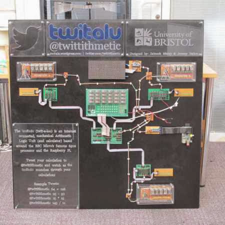
A Twitter Connected Mechanical Calculator

Two students at the University of Bristol wanted to create a computer to demonstrate how ALUs work. The result is the TwitALU, a Twitter connected mechanical calculator.
The device uses a custom 7400 series ALU based on the famous MOS 6502 processor. Instead of doing the calculations on a silicon die, the ALU drives mechanical relays. This produces a nice clicky-clacky sound as the calculation is computed.
A Twitter Connected Mechanical Calculator
To start a calculation, you tweet @twittithmetic with your input. A Raspberry Pi is used to load the instructions into the ALU. Once the computation is done, it’s tweeted back to you and displayed on the Nixie tube display. It’s not efficient, or fast, but it does the job of demonstrating the inner workings of the device while doing simple math.
The device’s schematics are all available on the website, and are helpful for understanding how a simple ALU works. After the break, check out a quick clip of the TwitALU in action.
read the rest of article...

VFD Display Becomes an Amplifier

Born well into the transistor era of the late 80s, [Fernando] missed out on all the fun you can have with high voltage and vacuum tubes. He wanted to experience this very cool tech, but since you won’t find a tube checker down at the five and dime anymore, where exactly do you get a vacuum tube to play around with? [Fernando]‘s solution was to rip apart the vacuum fluorescent display from an old radio (Google Translate) and use that as a triode.
VFD Display Becomes an Amplifier
Inside every VFD is a filament, grid, and cathode – three simple elements also found in the triodes of just about every tube amp ever made. By applying a small voltage to the filament, a larger voltage to the cathode, and sending an audio signal to the grid, this triode amplifies the electrical signal coming from a stereo or guitar.
[Fernando] built his circuit on a breadboard, and with a little tweaking managed to get a fairly respectable amount of gain from parts salvaged from a radio. While using VFDs as amplifiers is nothing new – we’ve seen it a few times before, tube builds are always great to see, and bodged up electronics even more so.
read the rest of article...

DIY CNC Rotary 4th Axis

Here’s a great CNC hack that adds a ton of functionality, a DIY rotary 4th axis!
[Jim] had started this project over a year ago when he originally ordered the gearhead off eBay, but like many good intentions, sometimes projects just get pushed to the back burner until necessity forces action.
DIY CNC Rotary 4th Axis
That necessity was entering our Trinket Contest, and he decided to finish it off just so he could put a HaD logo on a piece of PVC for us!
Unfortunately it took him a bit too long, and he only finished it last week — but luckily he had a fallback plan, and submitted his CNC Etch a Sketch project instead, which won him a Trinket anyway!
The 4th axis uses a 276oz-in stepper motor which is directly coupled to a Harmonic Drive Systems 11:1 planetary gearhead. It’s extremely accurate, has minimal backlash, and by using a 10 microstepping Gecko stepper drive, [Jim] is getting about 61 steps per degree of rotation. Not bad for a home-made setup!
Check out his blog for a great write up on the project, and stick around after the break to see the 4th axis in action.
read the rest of article...

Reverse Engineering the Z80′s 16-bit Increment/Decrement Circuit

Increment and decrement. They sound like simple functions. But even the simplest functions can get quite complex in a microprocessor design. Ken Shirriff has written up a great blog post about his reverse engineering of the Z80′s 16-bit increment/decrement circuit. The Zilog Z80 was one of the most popular microprocessors of the 70’s and 80’s. It was used in many classic computers such as the Osborne 1. These machines would often use the Z80 to run the popular CP/M operating system.
The increment/decrement circuit is responsible for updating the program counter register during normal (non branch) operations. The increment/decrement circuit also handles the stack pointer register during stack operations, as well as several other functions. One might wonder why a separate adder would be used when the microprocessor has a big ALU available to it. The answer is twofold. First the ALU is already in use handling user math operations. Secondly the increment/decrement circuit has to be fast. A generic ALU just won’t be fast enough.
One classic adding circuit is a Ripple Carry Adder. Ripple Carry Adders get the job done, but they are slow. Note slow is measured in nanoseconds here – there are no clocks involved in the circuit. The whole thing becomes a classic combinational logic optimization problem. Each layer of logic adds a gate delay to the circuit. As the carry has to ripple through all 16 bits, there are 16 gate delays before the final result is available at the outputs. Delays like these are what limits the maximum clock speed for a given circuit.
The Z80 uses some tricks in its increment/decrement circuit. The first is Carry-lookahead. A carry-lookahead circuit will calculate the carry values directly from the inputs. This reduces the gate delays significantly, but it requires more real estate on the die. A second trick is the carry-skip circuit. Carry-skip calculates the result for groups of bits rather than each bit individually. Again, it will reduce gate delays, at the cost of real estate. The actual Z80 implementation uses a mix of both circuits. Several other “helper” circuits are also used. Surprisingly the Z80 has specific logic just to check for 1 (0×0001) on the internal address bus. This circuit is used during memory move loops to inform other parts of the chip that a loop is about to complete.
read the rest of article...