Interfacing with the HTC Desire Display and its Touch Panel

Part of [Linas]‘ submission to last year’s Cypress Smarter Life Challenge involved using the HTC Desire display and its touch screen. This particular phone includes a full-color active-matrix OLED (AMOLED) display that has a 3.7″ diagonal and a 480×800 resolution, resulting in a 252ppi pixel density. Using a MSO2024B oscilloscope, [Linas] originally started his adventure with the touchscreen by sniffing the I2C signals. As some math was required to extract the data, he later found the HTC Desire source code and included it on his STM32F429 (so much for reverse engineering!).
Interfacing with the HTC Desire Display and its Touch Panel
After spending many hours searching for the AMOLED display and controller datasheets, [Linas] resorted to pay a company to get the resources he needed. He produced a custom-made PCB to provide the display with the required voltages, as well as offering a 0.1″ connector to interface with it. A RGB565 interface is used to communicate with the screen so only 65k out of the 16 million colors are used. You may download all the program files and datasheets in [Linas] write-up.
read the rest of article...

Testing The Limits Of Home PCB Etching

[Quinn Dunki]‘s Veronica, a homebrew computer based on the 6502 CPU, is coming along quite nicely. She’s just finished the input board that gives Veronica inputs for a keyboard and two old Nintendo gamepads. [Quinn] is building this computer all by her lonesome, including etching all the PCBs. She’s gotten very, very good at etching her own boards, but this input board did inspire a few facepalming moments.
In an earlier post, [Quinn] went over her PCB etching capabilities. As demonstrated by the pic above, she’s able to print 16 mil traces with 5 mil separation. This is just about as good as you can get with homebrew PCBs, but it’s not without its problems.
Testing The Limits Of Home PCB Etching
[Quinn] is using a photographic process for her boards where two copies of a mask is printed on an acetate sheet, doubled up, and laid down on a pre-sensitized copper board. The requirement for two layers of toner was found by experience – with only one layer of toner blocking UV light, [Quinn] got some terrible pitting on her traces and ground planes.

Two photographic masks means the masks must be precisely aligned. This example shows what happens when the acetate sheets are ever so slightly misaligned. With a 5 mil gap between traces, [Quinn] needs to align the masks to within ±2.5 mils; difficult to do by eye, and very hard once you factor in flexing and clamping them down to the copper board.

Even when this process goes perfectly, [Quinn] is pushing the limits of a laser printer. When printing at 600 dpi, the pixels of the print are about 1.5 mils. While GIMP, printer drivers, and the printer itself have some fancy software to help with the interpolation, [Quinn] is still seeing ‘bumps’ on the edges of perfectly aligned parts. This is one of those things that really makes you step back and realize how amazing fabbing PCBs at home actually is. With most of the hardware for Veronica out of the way, it’s just about time for [Quinn] to start programming her baby. We’re not expecting a full-blown operating system and compiler, but those NES gamepads are probably crying out for some use.
read the rest of article...

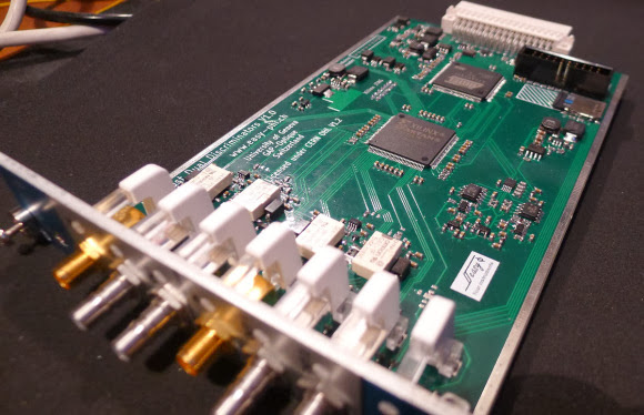
A Low Cost Dual Discriminator Module for the Easy-phi Project

A few months ago I presented you the Easy-phi project, which aims at building a simple, cheap but intelligent rack-based open hardware/software platform for hobbyists. With easy-phi, you simply have a rack to which you add cards (like the one shown above) that perform the functions you want.
A Low Cost Dual Discriminator Module for the Easy-phi Project
Recently my team finished testing our FPGA-based discriminator or “universal input” if you prefer. As easy-phi cards use a well-defined electrical signal to communicate with each other, we needed to make a card that would translate the different kinds of electrical signals from the outside, as well as perform plenty of other functions. It was therefore designed to have a 100MHz input bandwidth with an AC/DC coupled 50 ohm/high impedance input stage (x2) and 4 easy-phi outputs.

For this module, we picked the (old) spartan3-an FPGA to perform the different logic functions that may be needed by the final users (high speed counter, OR/XOR/AND, pulse creation,…). Using the cortex-m3 microcontroller present on the board, it may be easily reconfigured at will. All design resources may be found on our Github, and you can always have a look at our official website.
read the rest of article...